Sidebar
Table of Contents
DAX ESP32 Nodes
DAX ESP32 Nodes are various custom hardware devices that run on a common firmware platform with the ESP32 microcontroller. These devices were created to work with DAX Home Automation and to control my custom lights.
On startup, the device checks its internal configuration memory to see what type of device it has been configured as (defaulting as a DAX Lamp). Based on this device type, the firmware will configure the drivers to talk to the various hardware peripherals.
Below is a block diagram of a universal ESP32 Node - items with a dashed border are optional depending on the type of device


Connectivity
The DAX ESP32 nodes can use both WiFi and Bluetooth Low Energy connectivity simultaneously. The “radios” command used to enable or disable WiFi and/or BLE. Stand-alone DAX lamps that do not interface with DAX will have both radios disabled. For most devices, WiFi is used to connect to DAX for remote commands over MQTT, and to download firmware updates over HTTPS. When BLE is enabled, the serial command interface is available over the BLE UART characteristic. This is to allow apps to locally control devices. By default, WiFi is enabled and BLE is disabled.
In order to uniquely identify itself, the DAX ESP32 node will generate a device ID based on it's MAC address. An example device ID might be “daxLight-00112233”.
Device Control over MQTT with DAX
To establish an MQTT connection to DAX, the device does the following:
- The DAX ESP32 node tries to connect to WiFi using previously stored credentials
- If no credentials found, or the known SSID is not in range, the ESP32 will broadcast in AP mode using AsyncWiFiManager.
- The user can connect to the ESP device directly with a laptop or phone and select the correct WiFi SSID and password in a web browser
- The WiFi crednetials can also be manually loaded over serial with the command “setwifi ssid password”
- DAX Home Automation broadcasts an announcement message every 5 seconds on UDP broadcast. Any device on the local network can see this message if it is looking.
- When the DAX ESP32 node detects the UDP message, it connects to the MQTT server as advertised in the UDP message
- Upon connection to the MQTT server, the device does the following:
- Subscribe to topic “device/device_id”, which is used to send commands to only this device
- Subscribe to topic “device/device_id/status”, which is used to receive command responses from this device
- Subscribe to topic “device/all/device_type”, which is used to send commands to all devices of the same type. For example, LED lamps would subscribe to “dax/all/daxLight”
- Publish “alive! device_id” to “dax/announce” so that the DAX Home Automation server knows the device is online
- The device holds in a wait state to process commands or reconnect to MQTT/WiFi if needed
- When the DAX server receives the “alive” message, it determines if it recognizes this device, and if so, sends the “zone zone_name” command to the device_id topic
- The device then subscribes to “zone/zone_name/device_type”, which is used to send commands to all devices of the same type and in the same zone
OTA (Over the Air) Firmware Updates with HTTPS
One thing I have learned during my career (and with my previous sensor network) is that remote firmware updates are essential to maintain progress with IoT devices. The ability to perform a DFU (device firmware update) OTA (over the air) was one reason for selecting the ESP32 microcontroller. The OTA process uses a combination of MQTT (or a local serial command) and HTTPS for downloading firmware updates.
The HTTPS host name used for firmware updates is configured on my local DNS server to point to the IP address of the DAX Home Automation server. The firmware has the root CA (certificate authority) manually inserted in the source code.

- The command “otaupdate” is sent to the device over MQTT (or local serial console). The daxMQTTDeviceHost module handles this.
- The device makes an HTTPS GET request to the web server
- The request will look something like this: “/daxHome.fwbin?t=daxEspNode?cv=15”, which indicates it is currently using daxEspNode version 15
- The daxHome module handles the request and checks the directory file names to see if it has a newer version. It sends back the latest version and file name
- If the latest version is newer than the current, the DAX ESP node will send a request for the bin file.
- The node will download the file over HTTPS and apply the update automatically
- The node will send an MQTT message with a status message after completing
- The status message will inform the server if the firmware update was successful or the error code if the update failed
Device Types
Device type is configured with the “setpcb” command over serial or MQTT. All of the devices below run the same firmware.
DAX Lamp / Ambient Light (2016)
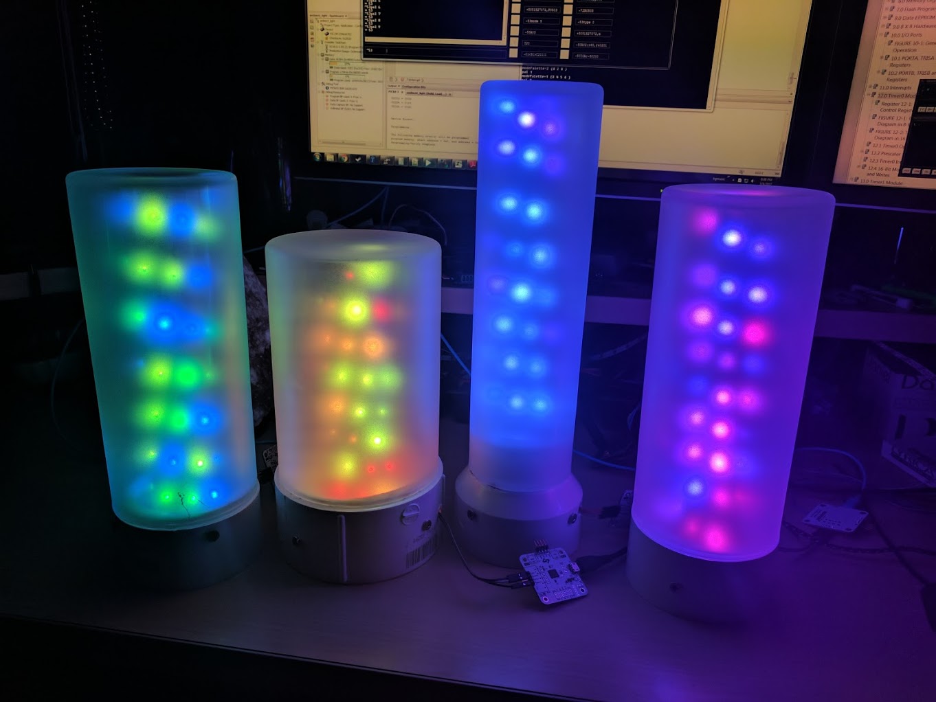
DAX Lamps are the first and simplest devices that I made. Typically only a USB power input and 3 pins for the LED strip are required. Onboard they only have an ESP32 module, a 3.3V LDO, a micro USB connector, and a few passives. I have made several variations of these PCB's in order to fit different types of physical lamp configurations.
The 3 LED output pins are 5V, data out (@3.3V), and ground. Although the WS2812B requires 5V logic, I have found that the ESP32's 3.3V logic is able to drive LED strips just fine without any kind of logic level converter.
These boards also contain 4 pins that can be configured as capacitive touch buttons and can either locally control the lights on the node, or they can send commands back to DAX to control the lights in the entire room.

DAX Switchpanel (2018)
The Switchpanel is a board I made to control other DAX devices in different rooms. It has 4x capacitive touch buttons, 4x single color status LEDs above the touch buttons, 4x WS2812B RGB LEDs at the top, and a piezo buzzer on the back.
Pressing a button on the switchpanel will make the board beep and the status LED above the button will light up. The Switchpanel the sends a message over MQTT to the topic “dax/device_id/btn” with the value “BTN1”, “BTN2”, etc.
The built-in behavior of these buttons is to operate all devices in the same zone. So if I press the “light on” button, all of the LED lights in the same zone will turn on. If I press the “sound on” button, white noise will begin playing on any daxAudio device in the same zone. No configuration is required. I can add these devices to another room by simply assigning them to a different zone.

DAX Audio (2020)

I like to play particular white noise audio files sometimes in my bedroom or workshop, and I also like alerts and chimes to play when various events occur. I have been using serialMP3 modules for this purpose, but those boards have a lot of parts (including a $20 codec that is difficult to find now) and require a nalig radio module to operate. With the I2S capabilities of the ESP32, I have been able to make a much simpler and cheaper alternative.
The ESP32 is a powerful 240 MHz dual-core microcontroller. This is fast enough to read wav file samples directly from a microSD card and output the data as I2S. It's also fast enough to do software MP3 decoding into I2S. The I2S data is outputted to either a MAX98357A 2W amplifier or a PCM5102A DAC connected to a 3.5 mm socket, depending on the board version.
The amp version of the board (shown below) can be connected directly to a speaker.
MQTT commands are used to play, stop, and loop audio files. Additionally, there is a download command so the ESP32 can download a new sound file over HTTPS and write it directly to the microSD card.

Temperature Sensor (2015)
I'll be upfront - the ESP32 runs too hot to have a temperature sensor on the same PCB. Particularly when the device stays awake and connected to WiFi, any onboard sensor will easily climb up to 90 degrees when the room is at a comfortable 75 degrees.
This ESP32 board that I like to affectionately call “tank temp” has an HTU21D temperature sensor at the end of a long, narrow section of the PCB. It was my attempt to keep the sensor far enough away as to more accurately measure the room temperature. Unfortunately, this technique is not effective and the sensor still reads way too hot.
Instead, I use DS18B20 1-wire temperature sensors connected to one of the headers. These sensors have enough physical distance that they can be used to more accurately measure ambient room temperature.

Downloads
- DAX Firmware (coming soon)
Writeup: Sep 2023
Page Tools
