Sidebar
Table of Contents
Low Power Projects with Nordic Semiconductor
While working for MapLarge, we started investigating wireless SoC's that could provide the lowest possible power consumption. I found Nordic Semiconductor SoC's to be the best choice because of their ability to draw extremely low amounts of power in sleep, there are ample amounts of documentation, SDK examples and user examples out on the open web, and the parts have also been somewhat adopted by the open source communities. We built a variety of products with Bluetooth Low Energy, LTE-M, GPS and LoRa radios. We also spent considerable time learning and using Zephyr RTOS to obtain low power. Below are some of my favorite boards that I made for Nordic chips.
Bluetooth Beacon (2021)
This Bluetooth Beacon was the simplest device we made, as it had only one SoC. The goal was to make a small device for basic sensor readings using BLE beacons, powered with a coin cell battery maximum battery life. At this point I have had several of these devices running since Oct 2021, so they have over 2 years of battery life. It's sleep current draw is 5 uA @ 3.0 V.
- Laird BL654 module for nRF52840 BLE SoC (the module allows for a much smaller footprint)
- CR2032 replaceable battery
- Sensirion SHTC3 temperature and humidity sensor
- Crocus CT8132SK Tunnel Magneto-resistance (TMR) digital magnetic sensor
- LIS2DW12 accelerometer
- Push button (hold to enter config mode)
- RGB LED
- Waterproof case for mounting or keychain connection
![]()
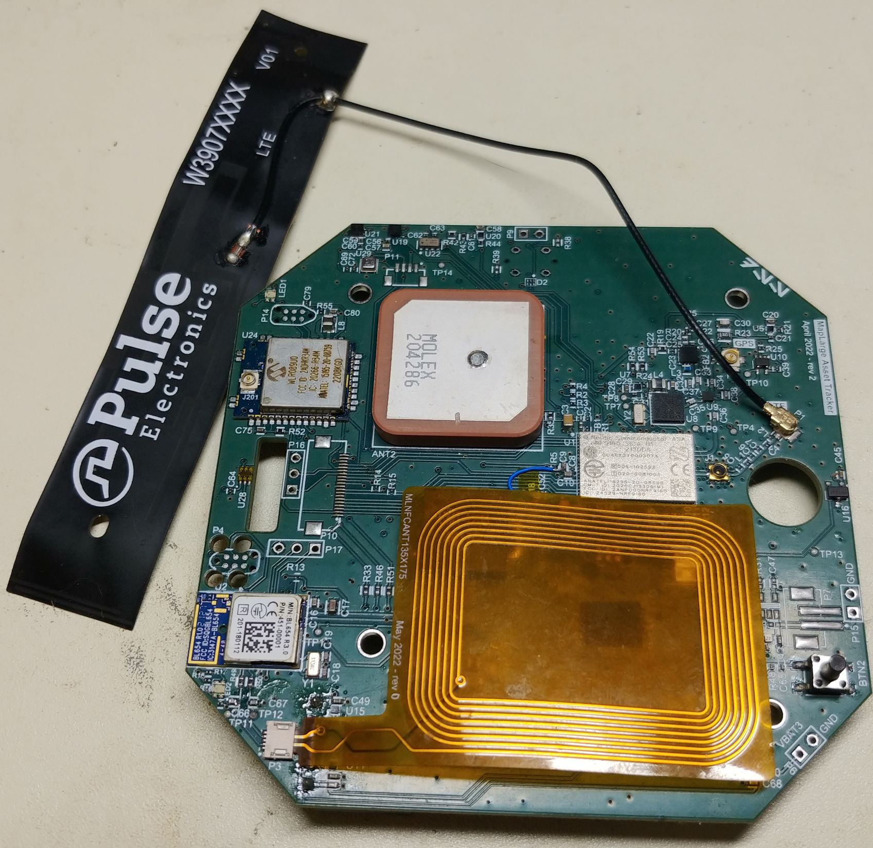
LTE Asset Tracker (2022)
The LTE asset tracker as a much larger device that combined multiple radios into this IoT device. The main application ran on the nRF9160 LTE SoC, while the nRF52840 allowed for BLE connectivity to apps in addition to scanning for other BLE beacons to retrieve sensor data. There was also a Microchip WLR089U0 LoRa module for sending additional data over LoRa. This tracking device ran on either a rechargeable battery or 6 AA batteries for over a year of battery life. Its sleep current draw is < 100 uA @ 5V.
- nRF9160 LTE+GPS SoC
- LTE-M operation for main data reporting
- Laird BL654 module for nRF52840 BLE SoC
- Same SHTC3, LIS2DW12, and CT8132SK sensors as above
- TSL25721 light sensor, BME280 temperature, humidity and pressure sensor
- uBlox ZOE-M8Q for superior GPS performance as well as simultaneous LTE + GPS operation
- Custom flexible NFC antenna for easy BLE pairing
- nanoSIM slot
- microSD slot
- Onboard flash memory
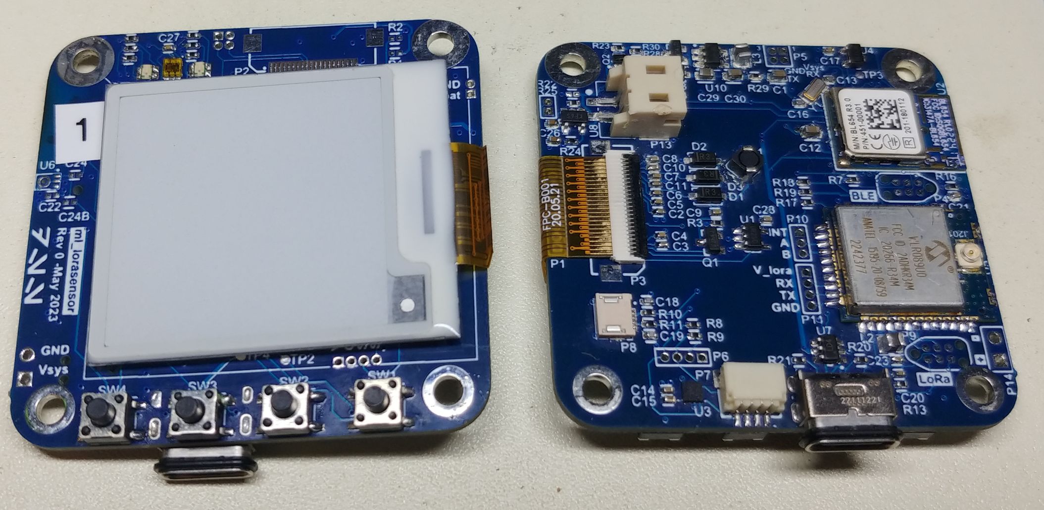
BLE + LoRa Sensor (2023)
We had a proposal for a project that involved both BLE and LoRa, but it required some kind of display and no need for LTE. So, I designed another board that had only the nRF52840 and WLR089U0 and added an e-ink screen. This monochromatic screen only draws power (about 10mA) while it is updating the screen. This is the perfect screen for a device that only needs to occasionally update the screen. Unfortunately this project never made it off the ground so all I have is this prototype board. Maybe I will find another use for it some day.
- Laird BL654 module for nRF52840 BLE SoC
- Same SHTC3, LIS2DW12, CT8132SK, TSL25721, and BME280 sensors as above
- 1.54“ E-ink screen (AES200200A00-1.54ENRS)
- Waterproof USB-C connector for charging and data transfer
- Rechargeable 400 mAH Li-po battery
- RGB LEDs
- 4 pushbuttons for menu navigation
Favorite Embedded Projects 2015 - 2019
Here are a few of my favorite embedded projects from work and personal projects over the years 2015 - 2019.
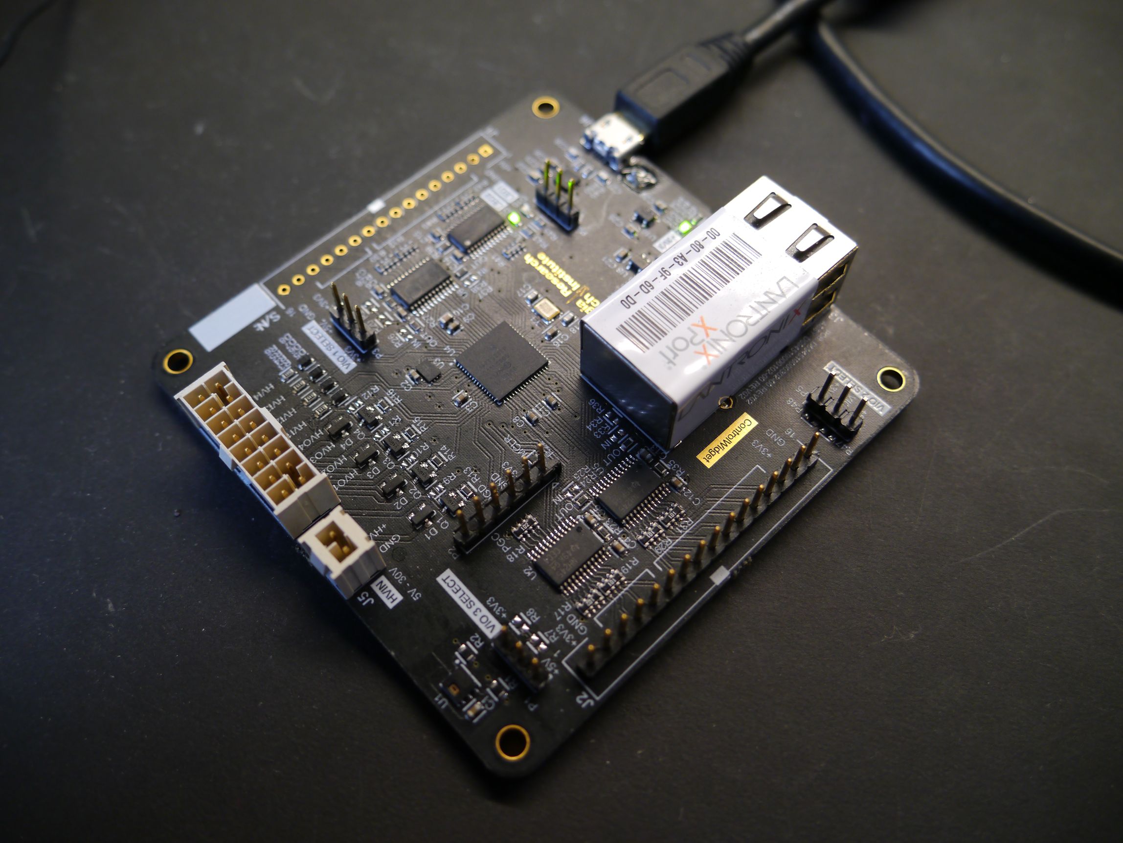
ControlWidget (2015)
The ControlWidget was one of my first widely used generic microcontroller platforms. Based on a dsPIC, the platform was used to control various RF devices, front panel connections (buttons and status LED's), high voltage power switching, and temperature monitoring. It supported the following features:
- Serial command interface to access GPIO and basic signal processing algorithms
- USB serial for connection to laptops or SBC's (single board computers)
- Lantronix Ethernet to Serial module for remote network connections (using the same serial command interface)
- USB or external 5V power
- Optional high voltage (9 - 24V) power connection for high voltage signal monitoring (input) and power switching (output)
- Jumpers to select 3.3V or 5V for each 8-bit GPIO bank
- Temperature and humidity sensor
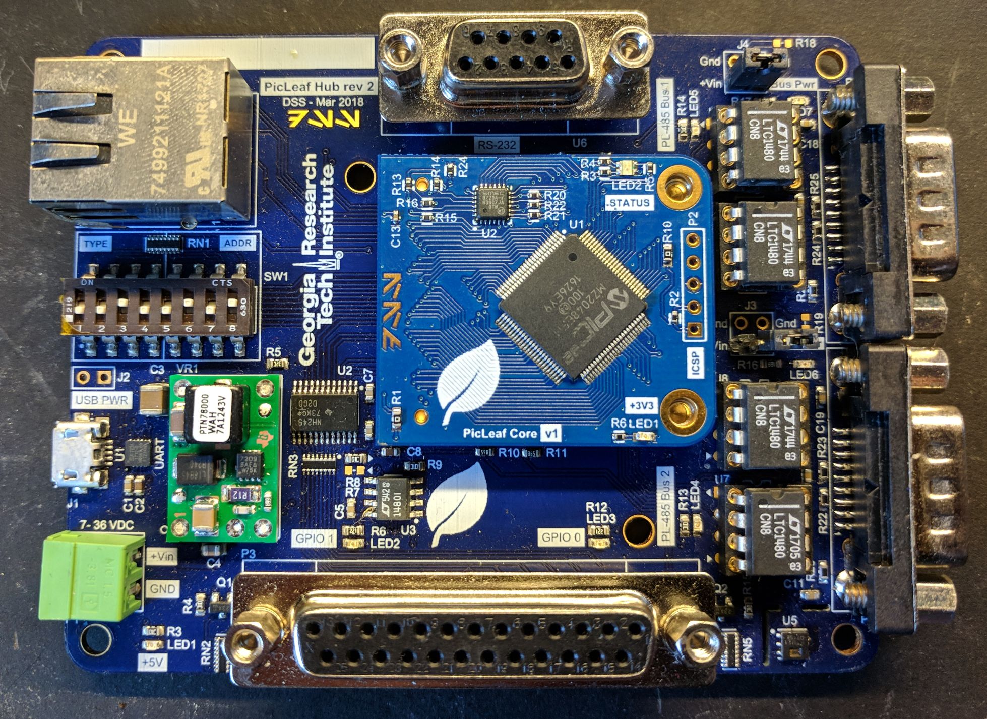
PicLeaf Hub (2017)
The PicLeaf system was an evolution in how I architected digital control systems. Instead of using a fixed controller board, I created a multiple devices that all communicated over an RS-485 network. The PicLeaf Hub (pictured below) had an Ethernet port and two isolated RS-485 networks. Other PicLeaf devices could be connected to each network, and device addresses and type are configured by DIP switches. Software would run on a tablet computer, and a configuration file would inform the system which devices should be connected on the network. The software would then dynamically generate a GUI to control each device.
The PicLeaf Hub features the following:
- PIC32 Core on detachable module with integrated LAN8720 Ethernet PHY
- Fully controllable over USB serial, custom TCP and UDP protocol implementations
- 7 - 36 VDC input with SMPS down to 5V
- Two GPIO banks, configurable as input or output and at 5V or 3.3V
- Two RS-485 network connections over DB-9 with replaceable driver IC's (they blew up sometimes)
- One RS-232 port for external device control
- USB Serial for debug connection (debug serial also available on UDP port)
- Temperature and humidity sensor
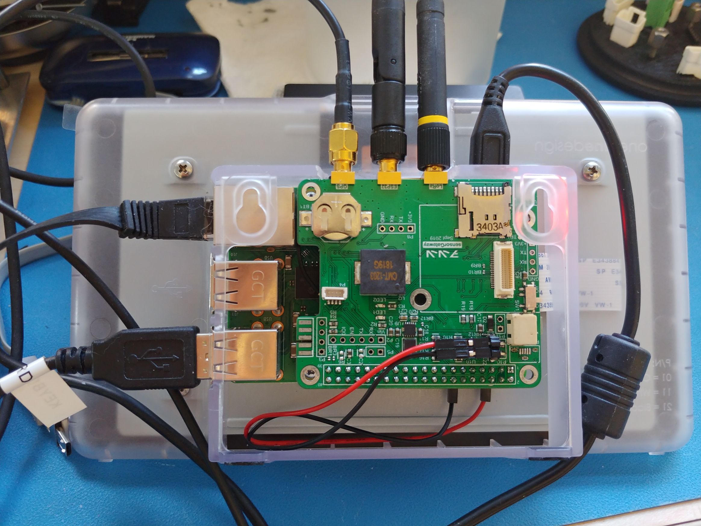
ESP32 PI Gateway (2019)
Sometimes you need the processing power and network connectivity of a Pi but also an embedded device to take care of some faster tasks. This was the basis for my ESP32 gateway, which helped managed a variety of inputs into a data collection service running on the Raspberry Pi. My ESP32 Pi Gateway featured the following:
- ESP32 microcontroller configurable for either WiFi SSID, Bluetooth Classic, or Bluetooth Low Energy device scanning. The ESP's radio was much easier to manipulate and significantly faster scanning was achievable on the ESP than what the Pi was capable of doing.
- uBlox GPS receiver with external antenna
- LoRa transceiver
- 3x SMA connections for each radio (ESP32, GPS, LoRa)
- Real Time Clock (RTC) module with backup battery
- microSD card for backup logging
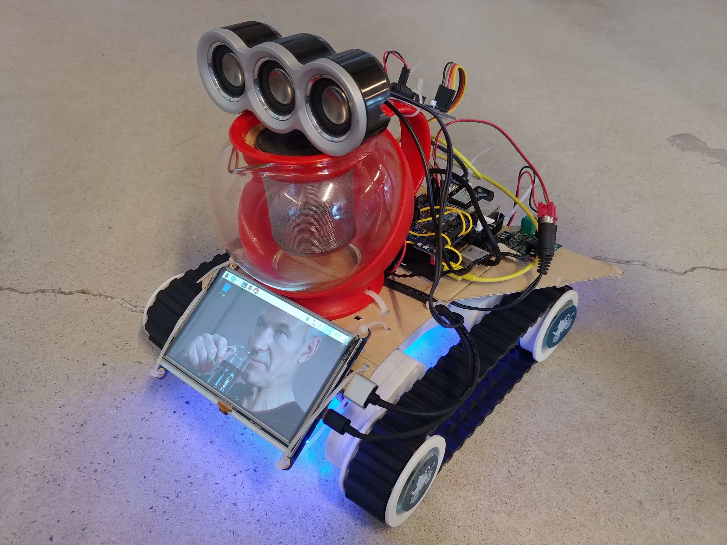
Tea Earl Gray Hot Bot (2019)
The Tea Earl Gray Hot Bot was my entry to the 2019 Alternative History Teacup Robot Race at DragonCon. This informal competition required a remote controlled robot with a tea theme to traverse an obstacle course. The robot features the following:
- Raspberry Pi core with Python script controlling the robot
- Adafruit motor controller on tracked robot base
- HDMI screen to display picture or video (why not??)
- Steam Controller for remote control
- 10W Audio amplifier with audio isolator to prevent noise
- Fancy DAX Lights on the bottom for a cool effect
- 6 quotes of Jean Luc Picard saying “Tea, Earl Gray, Hot” from Star Trek: The Next Generation.
The Tea Earl Gray Hot Bot won first prize that year!
Ten years of PCBs
The beginning of 2023 marked ten years of me making printed circuit boards. From Eagle to Altium, through hole to QFN, one layer FR4 with no soldermask to 8 layers with exotic cores, it's been a fun ride! I hope to keep making cool stuff in the years to come.
Here are some blanks of my favorite PCB's that I've made and kept over the years.
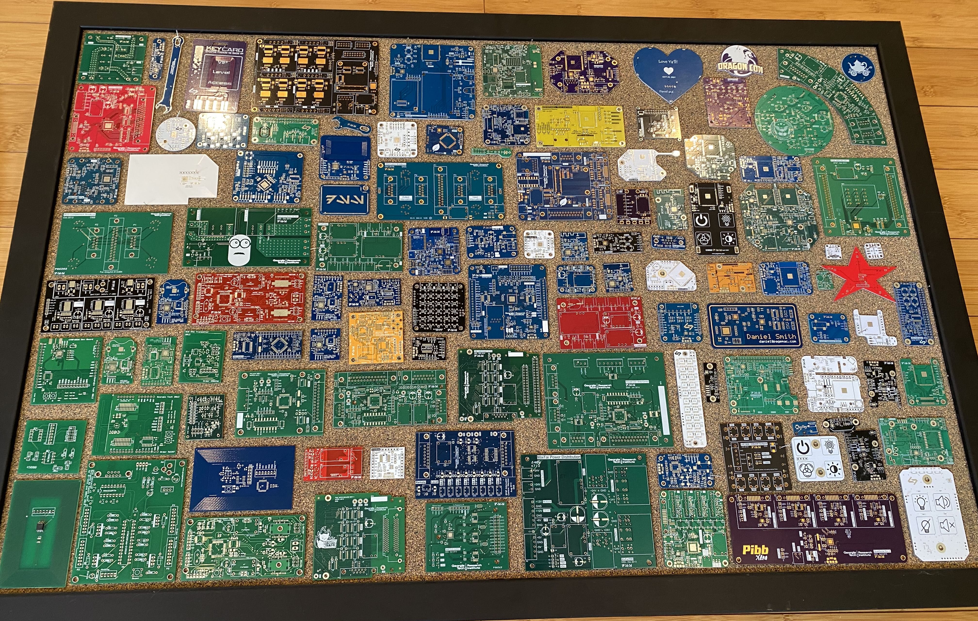
I made my first PCB in 2012 when I was still in grad school. The PCB was designed to be a clone of an RFID card. Shortly after that I made a small adapter PCB to use a BusPirate to program the cards. You can see these in the bottom left of the picture.
My first “real design” (as I felt, at least) was the DoorProgrammer. The project was to allow access control for one of the old WREK studios. It was my first project where I designed the PCB, assembled the board, wrote and programmed the firmware, and wrote the software to communicate with it.
Home automation updates
Since posting about my Apartment Security System, I have moved to a new house and made some nice additions. I now refer to it as a “home automation system”, since its uses have evolved beyond just providing security.
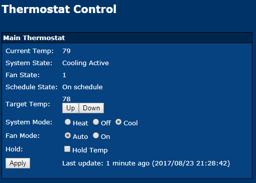
Thermostats
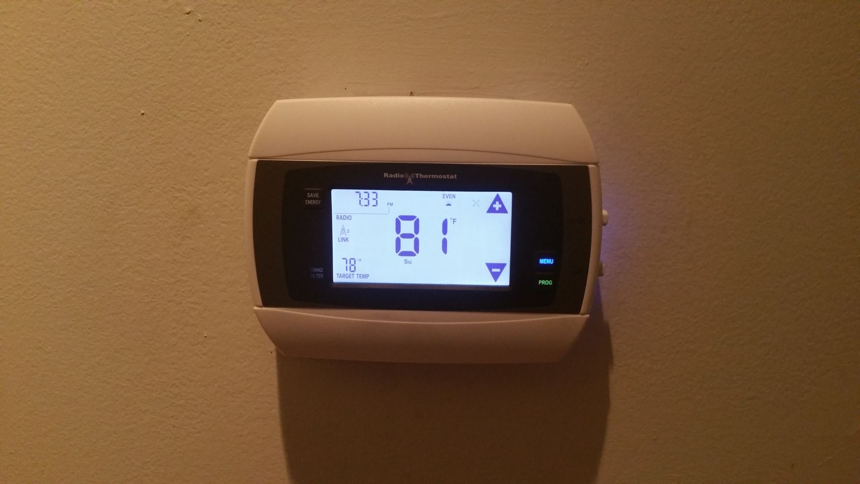
My new house has two thermostats, and I wanted to control both of them from my system. I briefly considered building my own thermostat, but decided I would like to be able to operate my AC when my automation system eventually has bugs/crashes/whatever. The next option was to buy a WiFi thermostat with an open API and control it that way. The Nest is the first thermostat that comes to most people's mind, and while it does have an open API, I didn't really want the other features or to pay brand name premium. Eventually, I found the Radio Thermostat CT-50 for $100. It has a completely open API (PDF) and there's even a Python library for it called radiotherm.
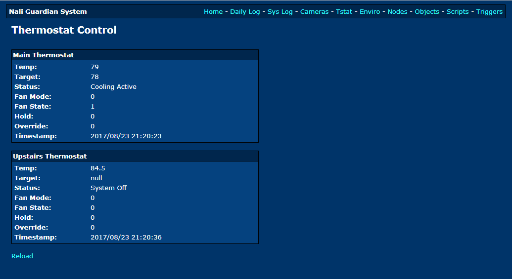
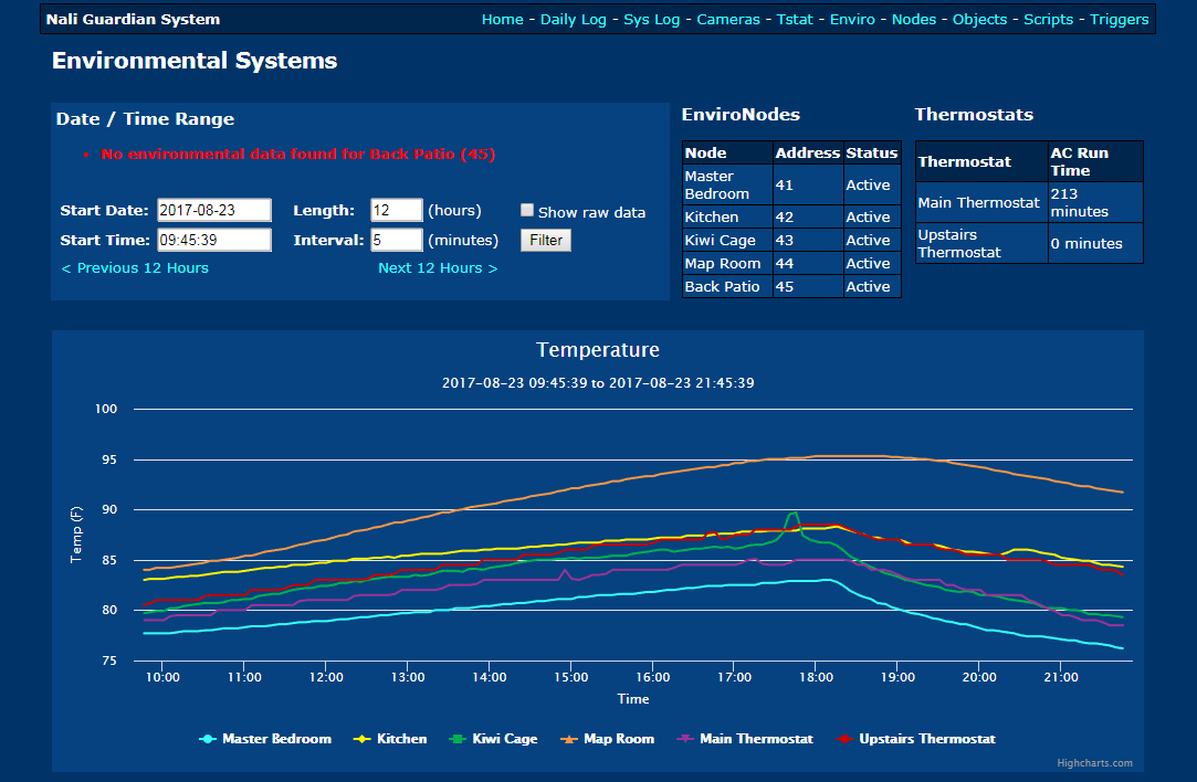
After hacking around with the Python library for a while, I was able to integrate it with my automation system. I replaced both of my thermostats with these models, and was able to add a web page to view the status of the thermostats. It was also not too difficult to add logging to the SQL database, so that the temperature display graphs included thermostat data right along side my EnviroNode data.
Unfortunately, the only way to control the thermostat with the system is by using the internal system commands. These commands can be accessed from the command line only, and I needed an easy way to execute these commands from the web. I decided to add a new feature, scripts. This would be how I began to control my thermostat.
Scripts
Although it has always been one of my ultimate goals to make the system extremely script-able with flow control, variables, the works (maybe some D++ integration!), the current script system just processes commands sequentially. Commands like “tstat 1 cool 76”, or “leds blink” or “sound 41” are the usual commands used in scripts, and it let me put together some useful and fun scripts.
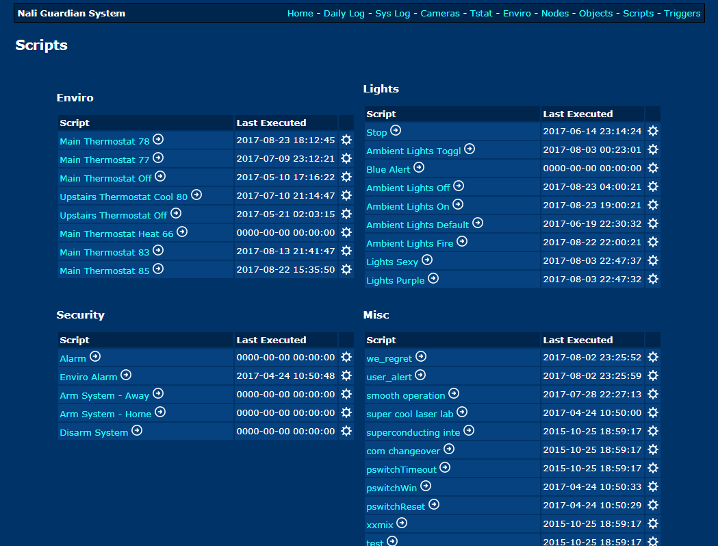
The scripts are simply text files stored in a database with an index number. To execute a script on the web interface, it calls a JavaScript function which makes an HTTP GET request to a PHP page, which then makes another HTTP request to a CherryPy webserver running with the automation system (can you tell I am not a web developer?). This is a really un-elegant solution, but it was the fastest way for me to get something running.
While implementing this system, I began to look into more “proper” ways of exchanging data between a web interface and a Python server, but with this script control also came an easier way to control my LED lighting…
LED Lighting
I made some pretty cool LED lights to go with my house. Originally based on code from my LED_Panel, I designed a new PIC24 micro board to control the WS2812B LED strips, in addition to APA101 LED strips. I bought a bunch of WS2812B LED strips, wrapped them around a PVC pipe, spray-frosted a glass vase and put the pipe in the middle.
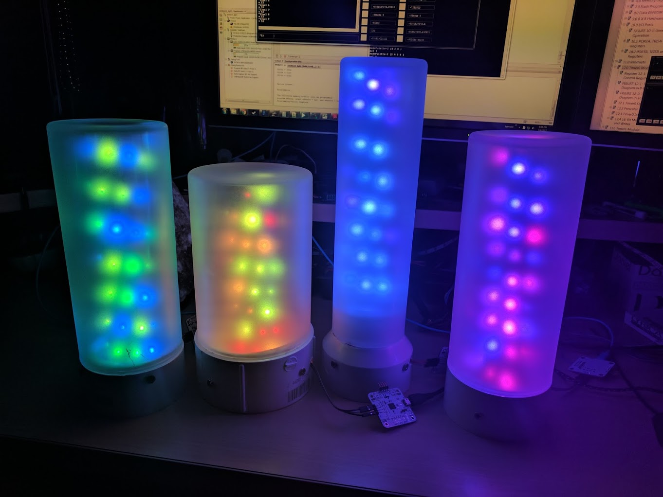
The lights have several modes, but they mostly run a hypnotic “ambient color mode” that pulses colors in a pleasant way. I have about 7 of these LED lamps around my house. They look super cool in person, and I definitely plan on doing a full write up as well as publish schematics and source code.
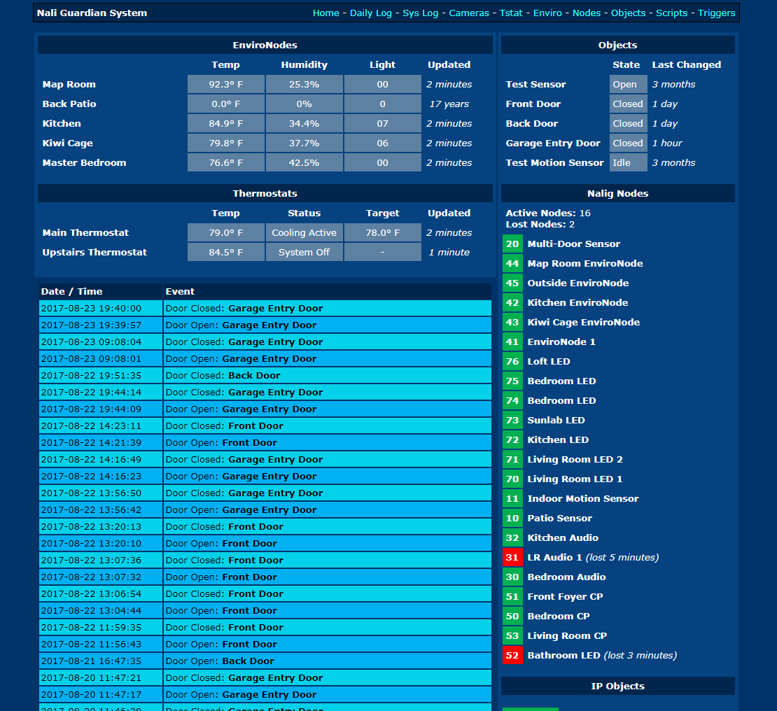
New Dashboard
Finally, a few months ago I began working on a new dashboard for my home automation system. With a little bit more JavaScript under my belt, plus playing around with CherryPy and JSON, I was able to pull together all of the system information and display it on a single page. I began re-working how the data was collected within the main Python program so that the entire system status could be summarized in a single JSON object. Using my crazy JavaScript-PHP-CherryPy work-around, I was able to get that JSON to the home page and display it with some oldschool HTML tables (oh god I don't even want to share this code).
Doing this made me realize I have a LOT more work to do. I need to make my system have full 2-way control using JSON and JavaScript, and I REALLY need to learn some modern web frameworks to make it pretty and more functional. I've been playing with some frameworks, and I'm going to continue to move forward so that I can control my system with the Raspberry Pi Security System Panel I have been somewhat working on. I've developed a prototype thermostat control that works, but it still uses HTML tables, and I really need to learn some of that fancy CSS so I can get my web skills out of the early 2000's…..
Bluetooth audio receiver antenna upgrade
I got a pretty nifty Bluetooth audio receiver with NFC to hook up to my speakers in the main room of my house. It works pretty well - the receiver stays on all the time so I can connect my phone to it whenever, and the 3.5mm audio out can be hooked into any powered speaker system.
There was one problem: the wireless range was pretty terrible. I could have my phone on me anywhere in the main part of the house, but if I walked into the kitchen or my bathroom with my phone in my pocket, the audio would stutter and lose connectivity.
The receiver has no external antennas, so I figured it must be using simple PCB trace antenna. Fancier devices might have multiple antennas for diversity, but I wasn't expecting that here.
I have this rule of thumb… a crappy antenna talking to a crappy antenna makes a bad connection. PCB trace antennas are great because they are basically free (part of the cost of the board) and don't add to a BOM (Bill of Materials), but they don't have the best performance. The 2.4 GHz antenna in your phone used for WiFi and Bluetooth will almost always be a terrible antenna. So… let's add a real antenna to this thing!
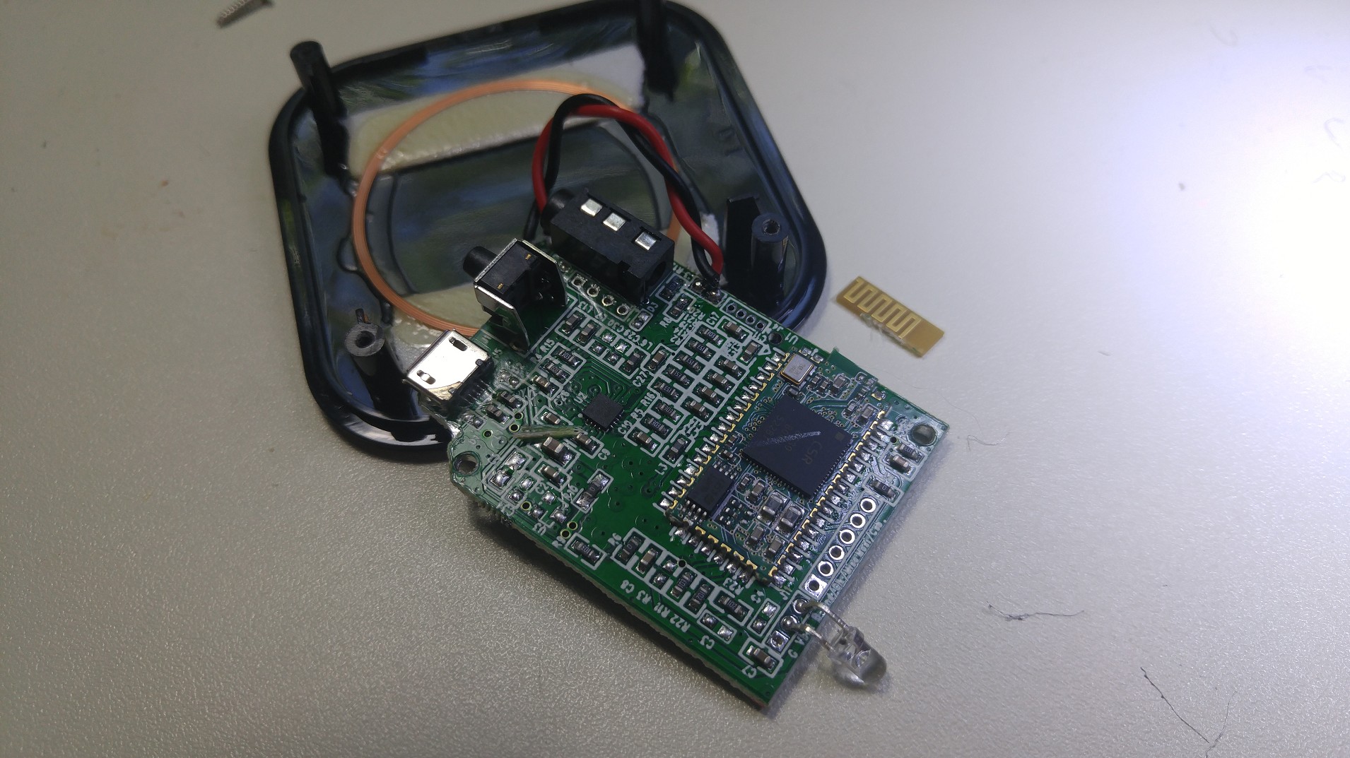
Inside the Receiver
Time to open this thing up and see what we've got…
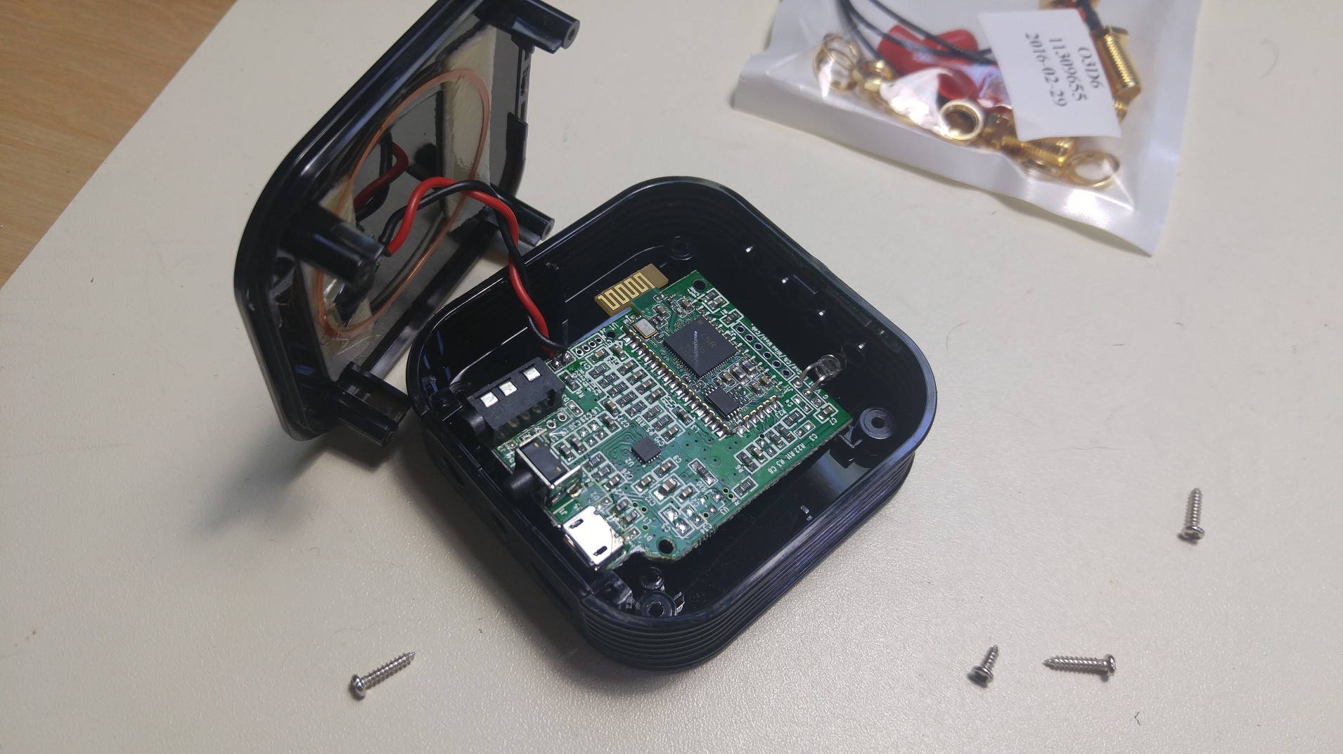
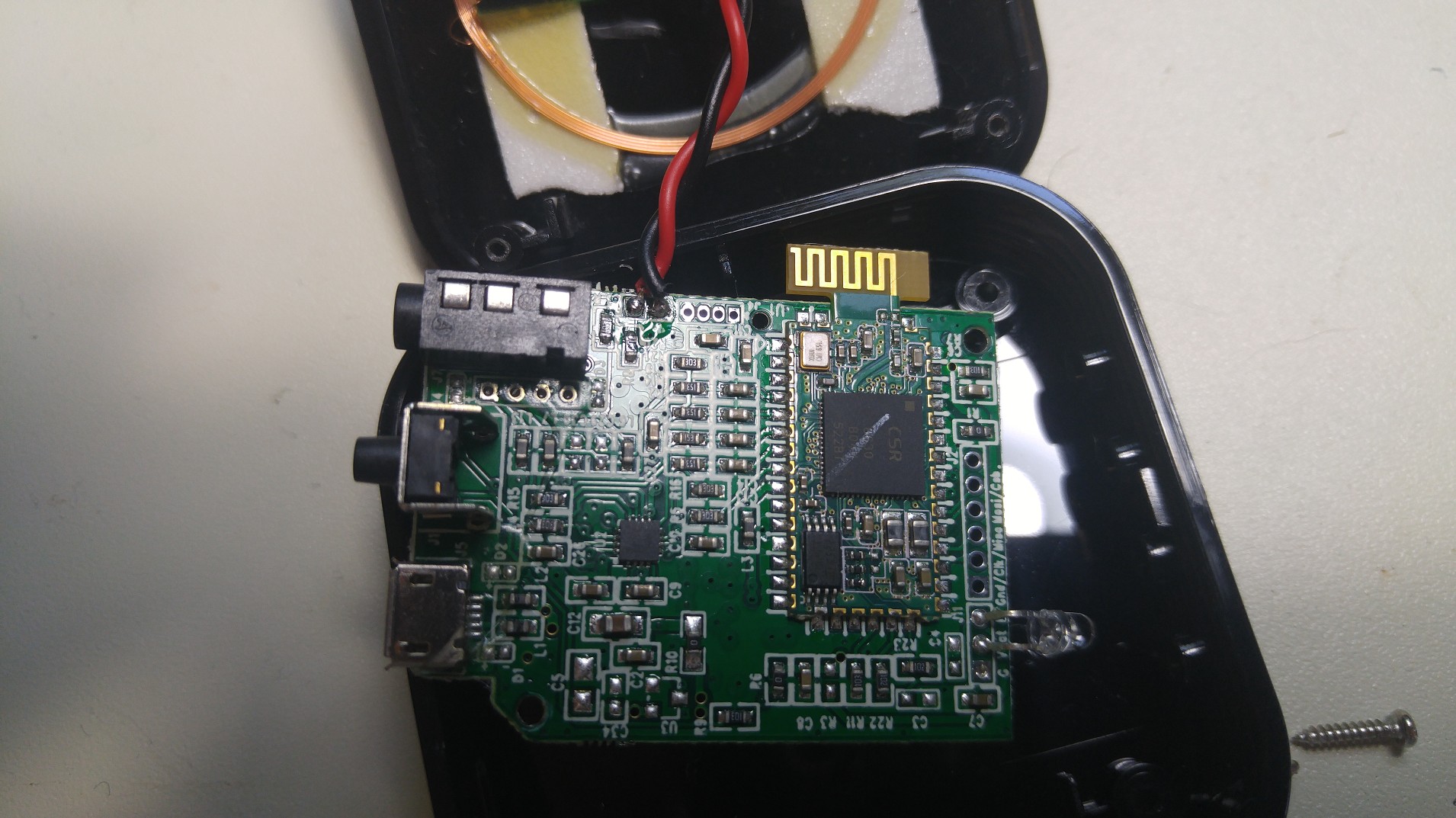
Just as I expected. A nice little wiggle antenna, similar to the one I used for my security system modules.
It appears that the designers used a Bluetooth module and stuck it on their main PCB. This is very convenient for an antenna modification, because the PCB trace antenna is sticking off the main board. (there's also some headers with SPI pin labels near them… looks like this board could be fairly hackable!)
One little snip with some cutters, and the old antenna is gone…
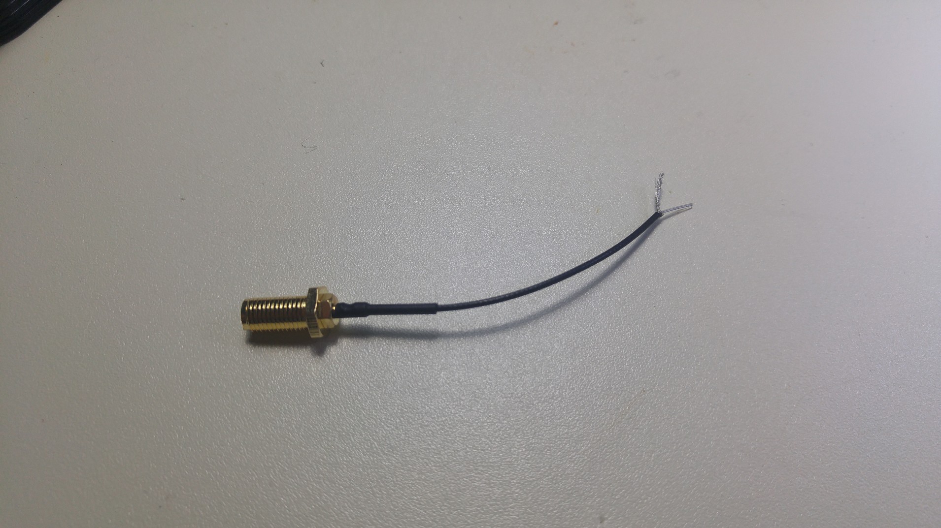
For the best performance, the new antenna should be outside the enclosure. An external SMA connection would be the most convenient, so I grabbed one of my SMA to uFL pigtail adapters I got on eBay. I cut the uFL connection off, and using an x-acto knife and microscope, I was able to strip the tiny coaxial wire. This tiny coax has an inner conductor (signal), a clear dielectric, a braided outer shield (ground), and an outer sleeve. By cutting just the outer sleeve, I was able to unravel the shield. Then I cut just a small amount of the inner dielectric, so a very small amount of the inner conductor was exposed. The SMA connector also had a locking nut, which means it could be easily mounted on the case by drilling a small hole.
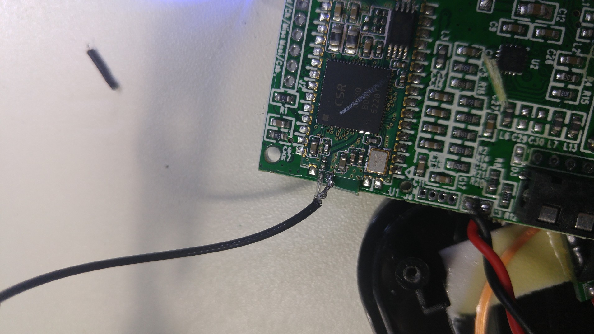
Next, I scraped off a small amount of the soldermask on the PCB trace that went to the old antenna. This is literally just scraping the top until there is enough exposed copper so that a solder connection can be made. I did the same on part of the ground plane next to this trace. With the aid of a microscope, I was able to solder the SMA connector to these exposed copper points. It's important to use as little solder as possible - we want the connection to be as smooth as possible to keep our impedance matched as close as possible. The individual wires for the ground and signal should also be as short as possible.
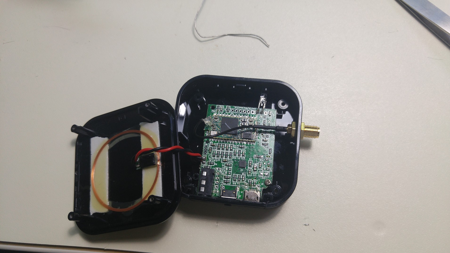
After that it was just a matter of putting it back together! This was actually more of a pain than I expected. The LED wouldn't go where it was supposed to and kept breaking off… but eventually, success! I paired the SMA connector with a 2.4 GHz antenna from DigiKey.
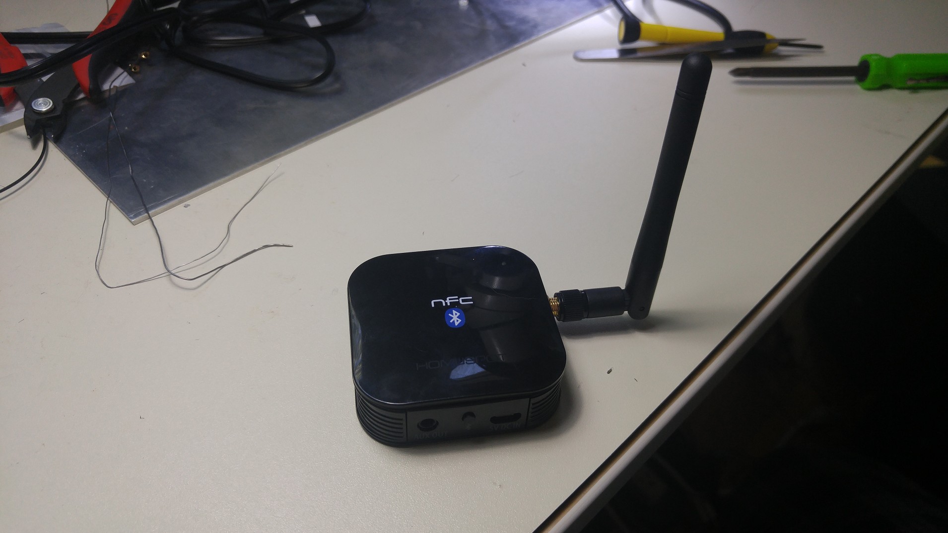
The receiver has significantly better range. I can keep my phone in my pocket and walk anywhere in my house - it still maintains the Bluetooth connection!
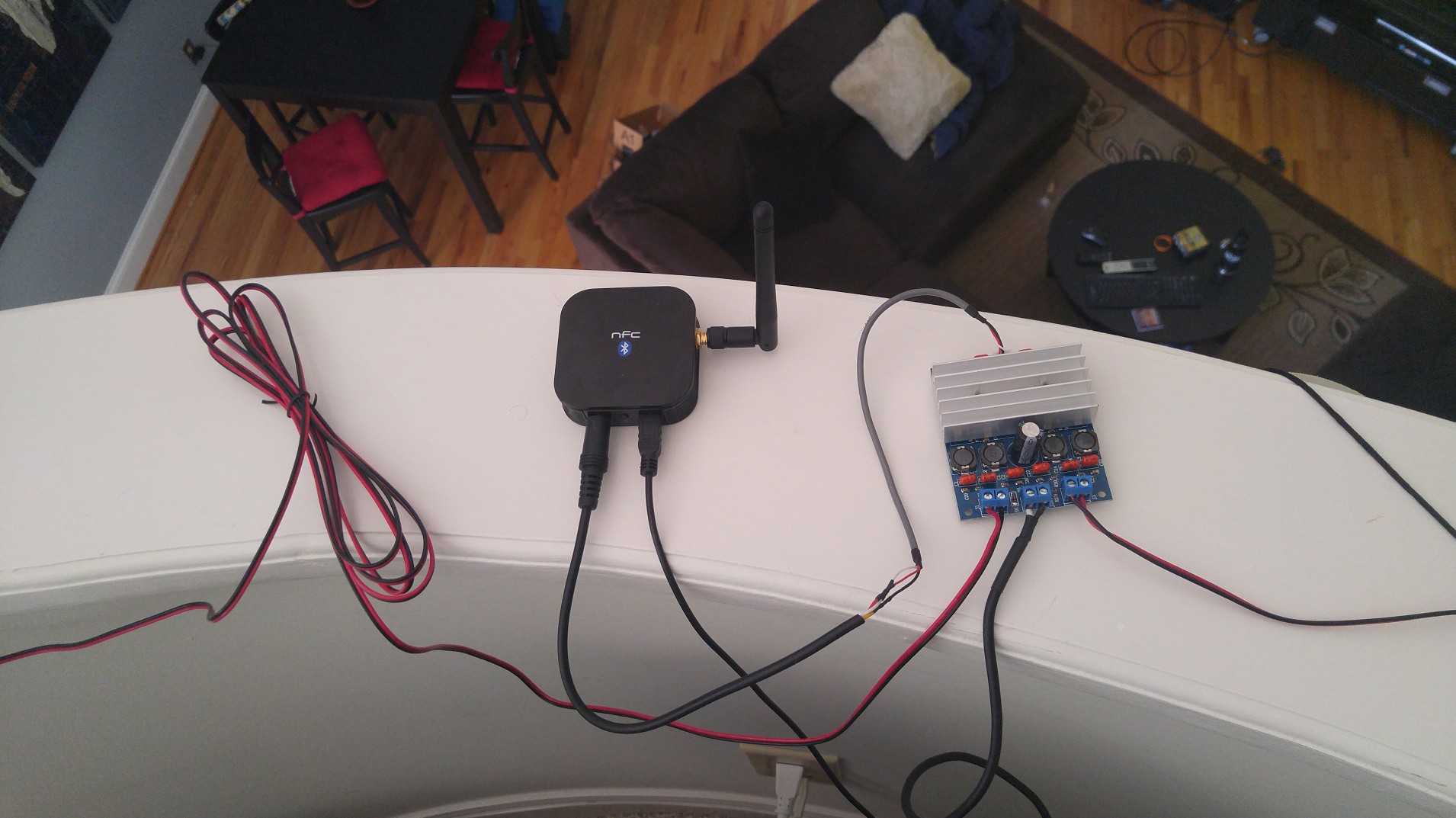
Add some speakers and an Amp
Okay, well, let's just make this a robust, cheap audio system!
The Dayton Audio B652 speakers are pretty awesome, especially for the price of $40 (and they often go on sale). I also got a cheap class-D audio amplifier on eBay based on the TDA7492 that pairs well with these speakers. (Parts Express also has a version of this amp). The audio cable needed a little splice to connect to the Bluetooth receiver. And there's no volume control - but you can control the input volume with the Bluetooth device.


And that's it! Now I just need some kind of 3D printed case to clean everything up…
Page Tools
