Sidebar
Table of Contents
Embedding Frigate into DAX Web Interface
In a recent adventure, I embedded Frigate into my custom DAX home automation system by placing an nginx reverse proxy in front of DAX and routing Frigate through a /frigate/ subdirectory. This solved same-origin and streaming issues while preserving HTTPS and full WebSocket/MSE functionality. The final result is a seamless, reliable, real-time camera interface inside DAX without modifying Frigate or the DAX python core. Only a few changes on the DAX web interface for embedding the iframe were required.

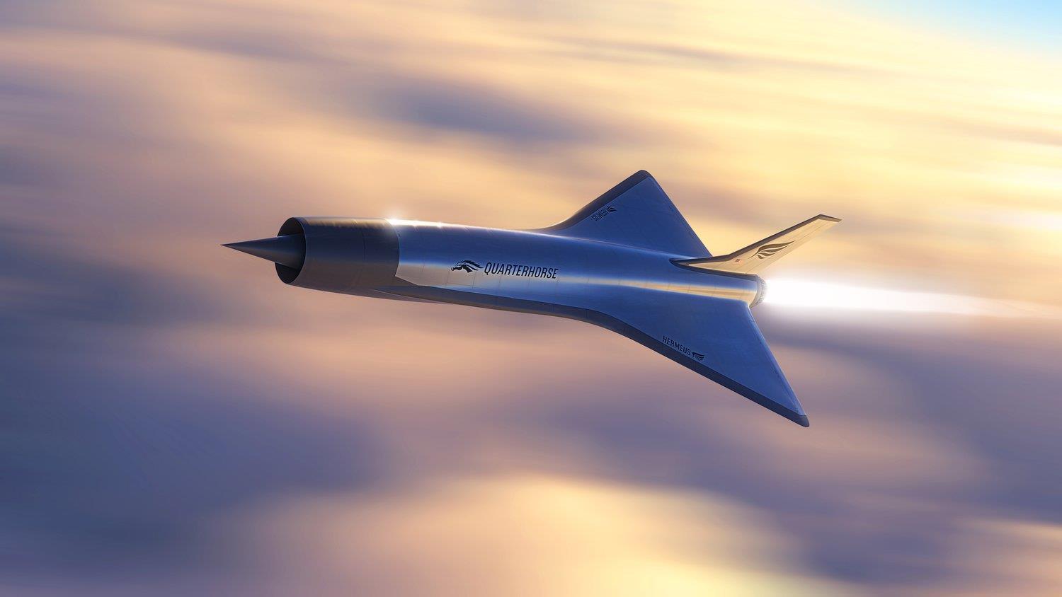
Hypersonic Avionics at Hermeus
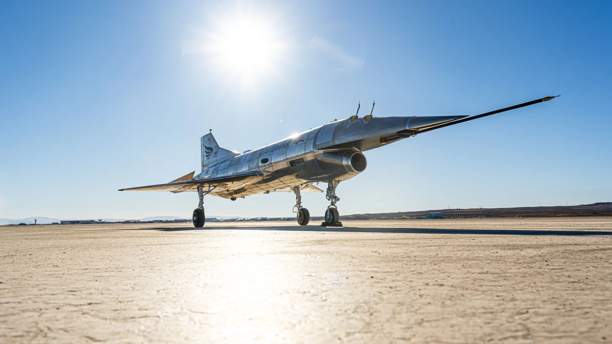
It’s been just over two years since I joined Hermeus as a Principal Avionics Engineer in November 2023, and it has been an absolutely incredible journey. For those unfamiliar, Hermeus is a defense-tech startup with a singular focus: the rapid design, build, and test of high-Mach and hypersonic aircraft. It's been quite a whirlwind for myself, moving from working on small, low-powered IoT devices to fast, experimental airplanes.
The core engineering philosophy at Hermeus is iteration. We are building progressively more complex aircraft to solve problems in hardware, not just in simulation. Before I started, the team had just completed the “Mk 0,” a non-flying, airframe-shaped ground test vehicle. It was a critical step for validating core subsystems—a J85 engine, full hydraulics, HV power, avionics, and comms—and exercising our ground testing operations and capabilities.
I came on board just as the team was pivoting to Mk 1, the aircraft destined to be Hermeus’s first to fly.
Getting Mk 1 Airborne
The goal for Mk 1 was straightforward but immense: prove we could design, build, and fly a jet-powered, remotely-piloted aircraft, FAST. As a Principal Avionics Engineer, my work was split between foundational electrical system design and a critical, time-sensitive triage of the RF systems.
Designing the Core Electrical Systems
As my first assignment, I was responsible for designing several key electrical subsystems from scratch.
- High Voltage (HV) Electrical System: I designed the complete HV system architecture, which powers the aircraft's fuel and hydraulics pump systems. This involved a battery, a generator, and associated power distribution. A major part of this effort was working closely with our battery vendor to develop a custom battery system that met our specific performance and environmental requirements. I then personally ran the entire V&V campaign, including all discharge tests, environmental acceptance testing, and full-scale integrated testing in our “Ironbird” to verify performance with the generator and motors. Finally, I supervised the installation and verification of the flight-ready system.
- Low Voltage (LV) Distribution: I also designed the primary LV distribution system. This was a separate network from the HV system, managing power for the avionics suite using batteries, switches, fuses, and an Electronic Circuit Breaker Unit (ECBU).
- Custom PCB Design (The RIDD): To meet a specific need, I designed a fully isolated, redundant DC-DC converter, which we dubbed the “RIDD” (Redundant Isolated DCDC). This was a full, from-scratch PCB design and verification effort.
Trial by Fire: Taking the RF Lead
As I was wrapping up the HV system integration testing, our RF lead departed the company. With my background in RF systems and flight testing from GTRI, I volunteered to take over the comms systems.
This was a critical moment. The vehicle was already in field testing, and the lack of a reliable command and control (C2) and telemetry (TM) links was delaying the entire program.
The vehicle had two redundant, independent radio systems, and both were failing.
- System 1 had severe multipath reliability issues.
- System 2 had unacceptable latency issues, making real-time control impossible.
Over the next few months, I systematically diagnosed the issues and resolved our communications problems.
- For the multipath issue, there were a variety of factors that brought the radio back into operational capability. In addition to some silly items like RF cable issues, I worked with the vendor to fine-tune the receiver's equalizer settings, which dramatically improved multipath performance.
- For the latency issue, after an arduous amount of testing, we ultimately determined that the radio system was simply not suitable for low-latency C2. We replaced it entirely with a much more reliable MIMO radio system, giving us additional reliability in multipath-heavy environments.
We also augmented the architecture, adding a SATCOM radio for beyond-line-of-sight (BLOS) capability and an additional line-of-sight (LOS) radio for redundancy.
One of the biggest process improvements I pushed for was adding better metrics to our software. Our telemetry monitoring was “blind” to RF performance, which made debugging performance issues very difficult. I worked with the software team to add real-time tracking of RSSI, packet reception rates, and other key metrics that were provided by the radios. This allowed us to stop guessing and start debugging with data.
With these new metrics, we ran dozens of tests. I wrote my own Python scripts to post-process and visualize the data. This analysis was key to building confidence and, eventually, getting all radio systems working reliably through low-speed and high-speed taxi testing.
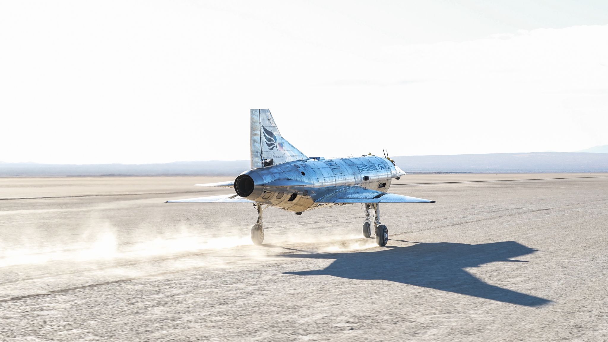
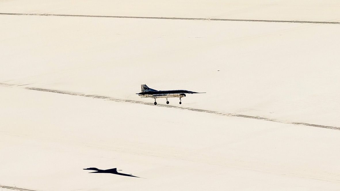
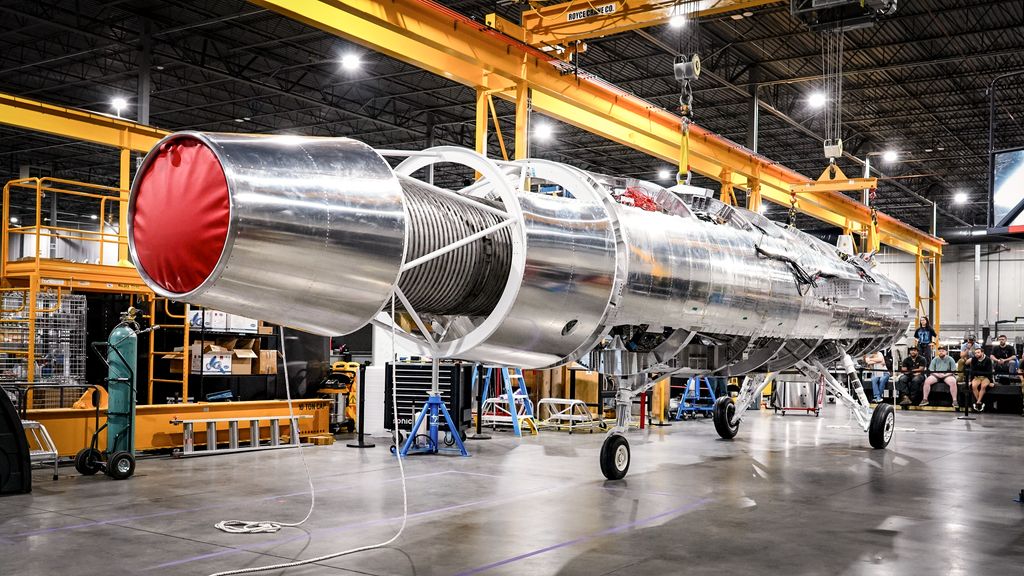
The Payoff: Mk 1 First Flight
On May 20, 2025, Mk 1 successfully completed its first flight. This was a monumental achievement for the company and a huge personal milestone. I'm incredibly proud to report that all the systems I was responsible for—the HV and LV power systems, the RIDD converter, and the entire C2/telemetry link—performed flawlessly.
Leveling Up: Mk 2.1
We barely paused to celebrate. Work was already well underway on Mk 2.1, our supersonic aircraft slated to fly in early 2026. Mk 2.1 is a much larger aircraft, equipped with a Pratt & Whitney F100 engine.
I am continuing my role as RF Lead, but my responsibilities also expanded.
- Core Avionics Tray Design: I took full design ownership of one of the core avionics tray assemblies. This single unit houses our radio systems, LV batteries, power distribution, transponders, and other critical avionics. I was responsible for designing all the electrical wiring, harnesses, and generating the complete documentation package. I also personally performed the V&V and environmental acceptance testing.
- Expanded RF Architecture: We added even more LOS and BLOS radio systems to Mk 2.1 to handle the expanded data requirements and challenging flight envelope.
- Cross-Disciplinary Coordination: I led the technical coordination for our RF hardware, working with our antenna engineer who is designing high-temperature conformal antennas and managing the procurement and design of our high-performance RF cables.
The entire process for Mk 2.1 has been a marked improvement from the scramble on Mk 1. Our methods, documentation, and integrated testing processes are substantially more mature. It’s the iterative development philosophy in action.
The pace at Hermeus is relentless, but the mission is clear and the engineering is deeply rewarding. We’re moving fast, and I can't wait to see Mk 2.1 take to the skies.
Low Power Projects with Nordic Semiconductor
While working for MapLarge, we started investigating wireless SoC's that could provide the lowest possible power consumption. I found Nordic Semiconductor SoC's to be the best choice because of their ability to draw extremely low amounts of power in sleep, there are ample amounts of documentation, SDK examples and user examples out on the open web, and the parts have also been somewhat adopted by the open source communities. We built a variety of products with Bluetooth Low Energy, LTE-M, GPS and LoRa radios. We also spent considerable time learning and using Zephyr RTOS to obtain low power. Below are some of my favorite boards that I made for Nordic chips.
Bluetooth Beacon (2021)
This Bluetooth Beacon was the simplest device we made, as it had only one SoC. The goal was to make a small device for basic sensor readings using BLE beacons, powered with a coin cell battery maximum battery life. At this point I have had several of these devices running since Oct 2021, so they have over 2 years of battery life. It's sleep current draw is 5 uA @ 3.0 V.
- Laird BL654 module for nRF52840 BLE SoC (the module allows for a much smaller footprint)
- CR2032 replaceable battery
- Sensirion SHTC3 temperature and humidity sensor
- Crocus CT8132SK Tunnel Magneto-resistance (TMR) digital magnetic sensor
- LIS2DW12 accelerometer
- Push button (hold to enter config mode)
- RGB LED
- Waterproof case for mounting or keychain connection
![]()
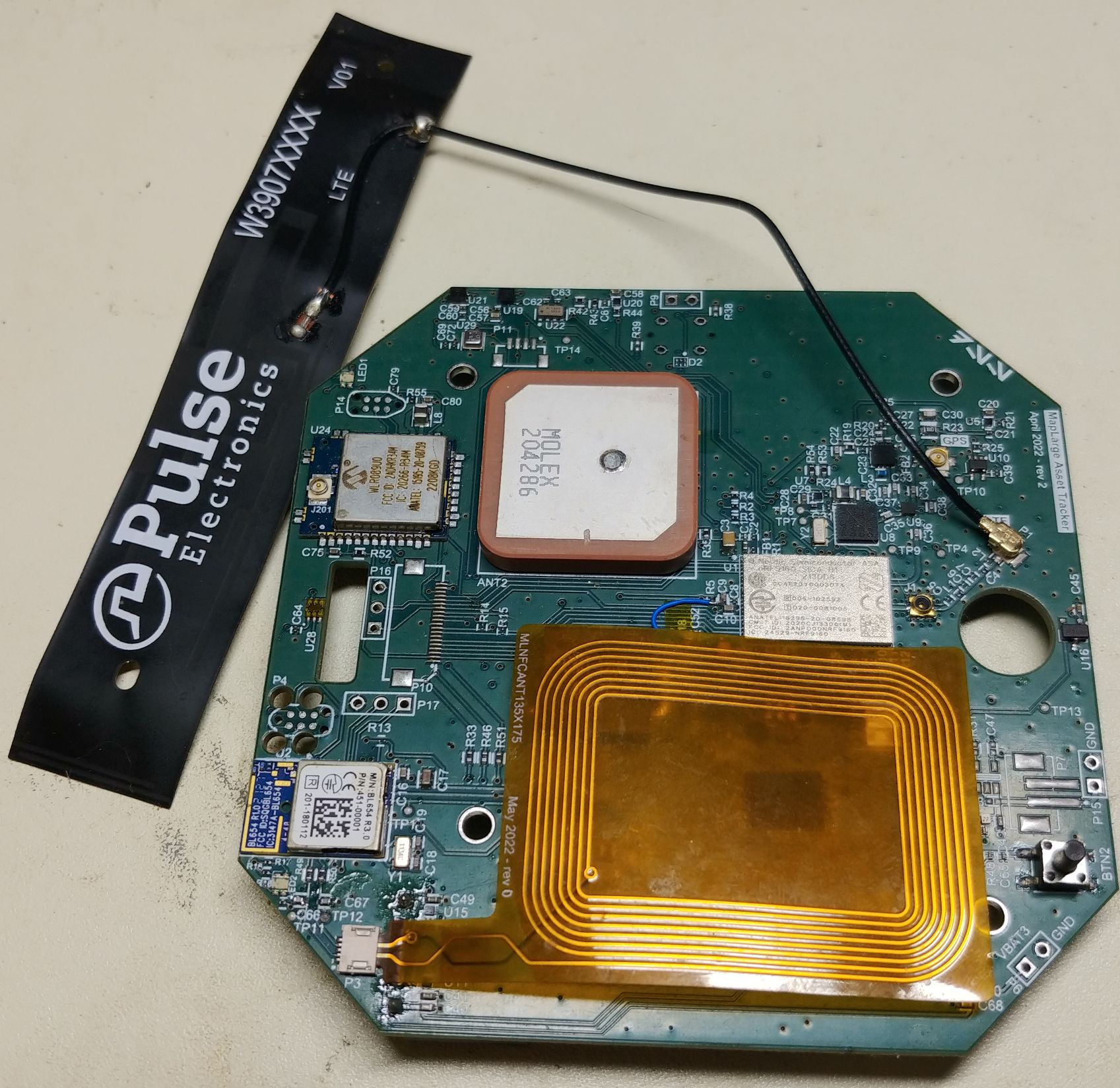
LTE Asset Tracker (2022)
The LTE asset tracker as a much larger device that combined multiple radios into this IoT device. The main application ran on the nRF9160 LTE SoC, while the nRF52840 allowed for BLE connectivity to apps in addition to scanning for other BLE beacons to retrieve sensor data. There was also a Microchip WLR089U0 LoRa module for sending additional data over LoRa. This tracking device ran on either a rechargeable battery or 6 AA batteries for over a year of battery life. Its sleep current draw is < 100 uA @ 5V.
- nRF9160 LTE+GPS SoC
- LTE-M operation for main data reporting
- Laird BL654 module for nRF52840 BLE SoC
- Same SHTC3, LIS2DW12, and CT8132SK sensors as above
- TSL25721 light sensor, BME280 temperature, humidity and pressure sensor
- uBlox ZOE-M8Q for superior GPS performance as well as simultaneous LTE + GPS operation
- Custom flexible NFC antenna for easy BLE pairing
- nanoSIM slot
- microSD slot
- Onboard flash memory
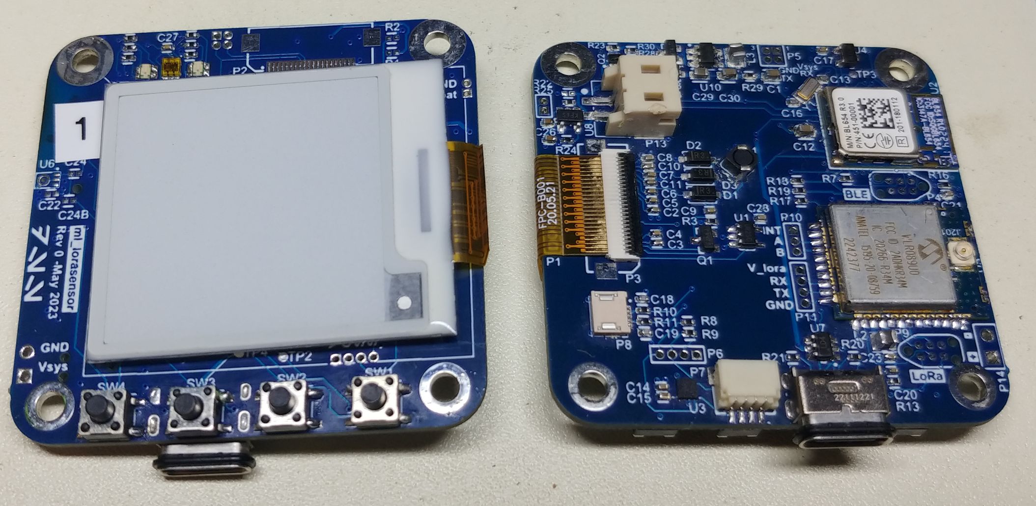
BLE + LoRa Sensor (2023)
We had a proposal for a project that involved both BLE and LoRa, but it required some kind of display and no need for LTE. So, I designed another board that had only the nRF52840 and WLR089U0 and added an e-ink screen. This monochromatic screen only draws power (about 10mA) while it is updating the screen. This is the perfect screen for a device that only needs to occasionally update the screen. Unfortunately this project never made it off the ground so all I have is this prototype board. Maybe I will find another use for it some day.
- Laird BL654 module for nRF52840 BLE SoC
- Same SHTC3, LIS2DW12, CT8132SK, TSL25721, and BME280 sensors as above
- 1.54“ E-ink screen (AES200200A00-1.54ENRS)
- Waterproof USB-C connector for charging and data transfer
- Rechargeable 400 mAH Li-po battery
- RGB LEDs
- 4 pushbuttons for menu navigation
Favorite Embedded Projects 2015 - 2019
Here are a few of my favorite embedded projects from work and personal projects over the years 2015 - 2019.
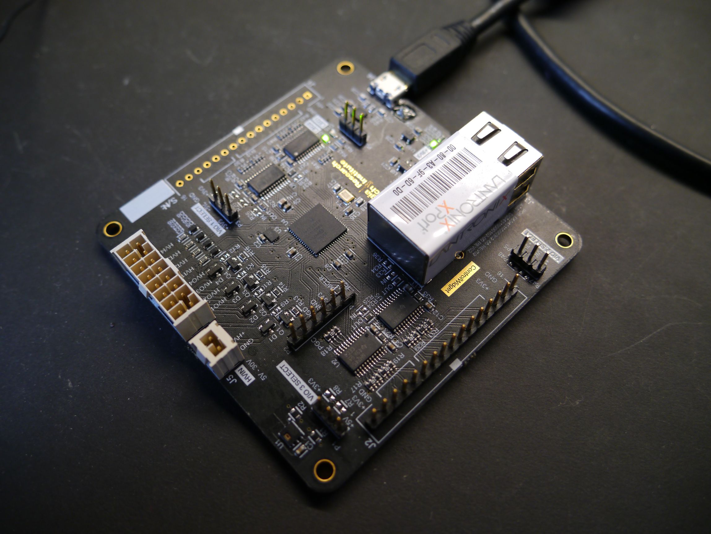
ControlWidget (2015)
The ControlWidget was one of my first widely used generic microcontroller platforms. Based on a dsPIC, the platform was used to control various RF devices, front panel connections (buttons and status LED's), high voltage power switching, and temperature monitoring. It supported the following features:
- Serial command interface to access GPIO and basic signal processing algorithms
- USB serial for connection to laptops or SBC's (single board computers)
- Lantronix Ethernet to Serial module for remote network connections (using the same serial command interface)
- USB or external 5V power
- Optional high voltage (9 - 24V) power connection for high voltage signal monitoring (input) and power switching (output)
- Jumpers to select 3.3V or 5V for each 8-bit GPIO bank
- Temperature and humidity sensor
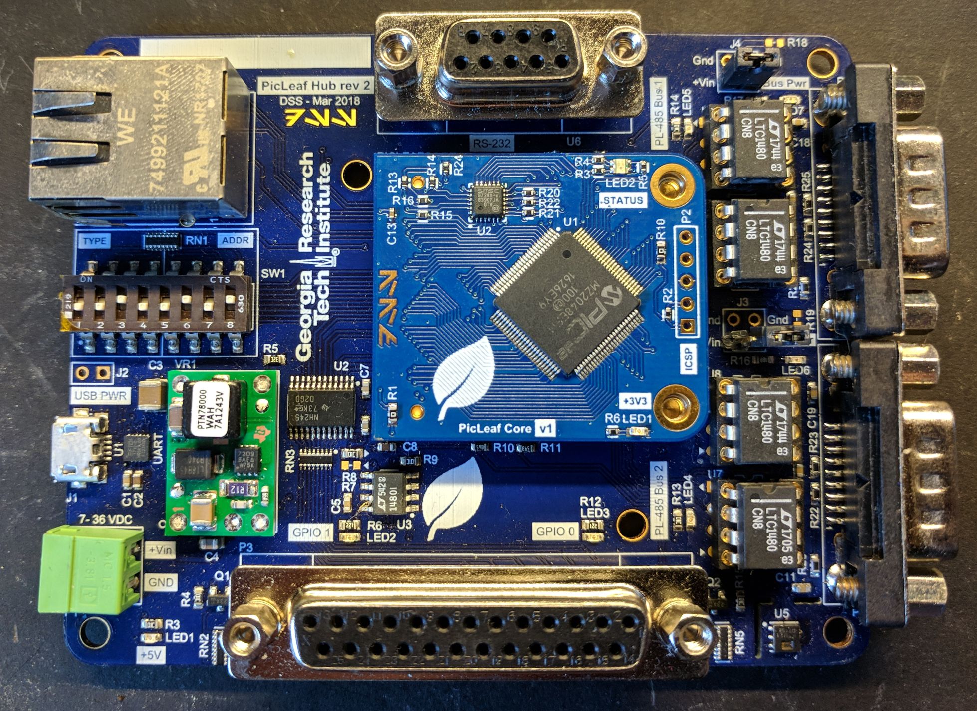
PicLeaf Hub (2017)
The PicLeaf system was an evolution in how I architected digital control systems. Instead of using a fixed controller board, I created a multiple devices that all communicated over an RS-485 network. The PicLeaf Hub (pictured below) had an Ethernet port and two isolated RS-485 networks. Other PicLeaf devices could be connected to each network, and device addresses and type are configured by DIP switches. Software would run on a tablet computer, and a configuration file would inform the system which devices should be connected on the network. The software would then dynamically generate a GUI to control each device.
The PicLeaf Hub features the following:
- PIC32 Core on detachable module with integrated LAN8720 Ethernet PHY
- Fully controllable over USB serial, custom TCP and UDP protocol implementations
- 7 - 36 VDC input with SMPS down to 5V
- Two GPIO banks, configurable as input or output and at 5V or 3.3V
- Two RS-485 network connections over DB-9 with replaceable driver IC's (they blew up sometimes)
- One RS-232 port for external device control
- USB Serial for debug connection (debug serial also available on UDP port)
- Temperature and humidity sensor
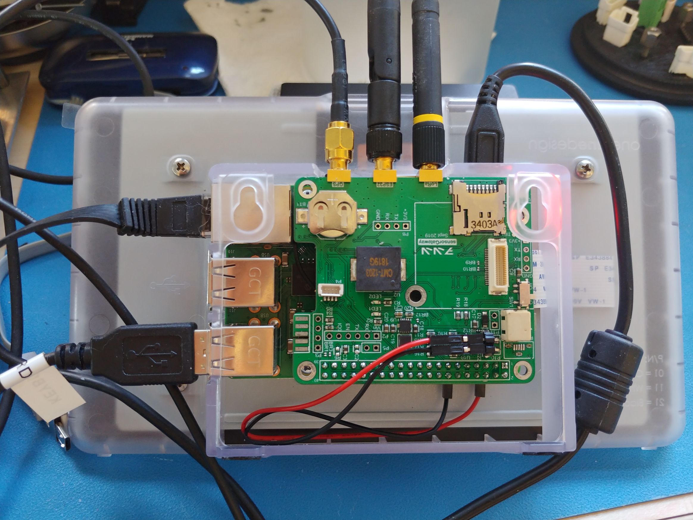
ESP32 PI Gateway (2019)
Sometimes you need the processing power and network connectivity of a Pi but also an embedded device to take care of some faster tasks. This was the basis for my ESP32 gateway, which helped managed a variety of inputs into a data collection service running on the Raspberry Pi. My ESP32 Pi Gateway featured the following:
- ESP32 microcontroller configurable for either WiFi SSID, Bluetooth Classic, or Bluetooth Low Energy device scanning. The ESP's radio was much easier to manipulate and significantly faster scanning was achievable on the ESP than what the Pi was capable of doing.
- uBlox GPS receiver with external antenna
- LoRa transceiver
- 3x SMA connections for each radio (ESP32, GPS, LoRa)
- Real Time Clock (RTC) module with backup battery
- microSD card for backup logging
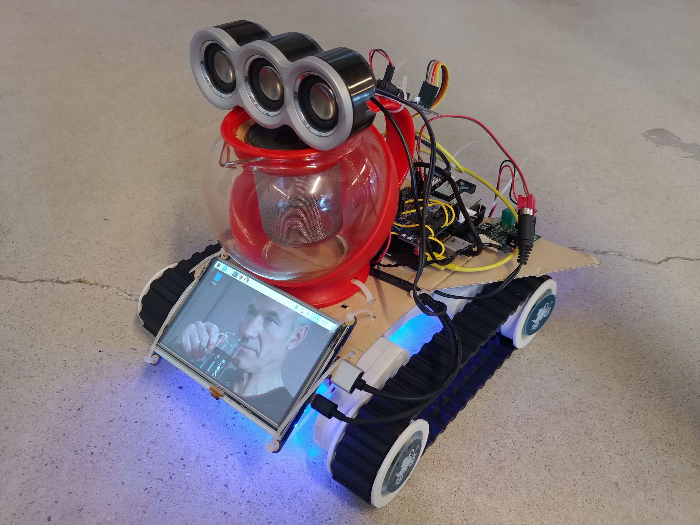
Tea Earl Gray Hot Bot (2019)
The Tea Earl Gray Hot Bot was my entry to the 2019 Alternative History Teacup Robot Race at DragonCon. This informal competition required a remote controlled robot with a tea theme to traverse an obstacle course. The robot features the following:
- Raspberry Pi core with Python script controlling the robot
- Adafruit motor controller on tracked robot base
- HDMI screen to display picture or video (why not??)
- Steam Controller for remote control
- 10W Audio amplifier with audio isolator to prevent noise
- Fancy DAX Lights on the bottom for a cool effect
- 6 quotes of Jean Luc Picard saying “Tea, Earl Gray, Hot” from Star Trek: The Next Generation.
The Tea Earl Gray Hot Bot won first prize that year!
Ten years of PCBs
The beginning of 2023 marked ten years of me making printed circuit boards. From Eagle to Altium, through hole to QFN, one layer FR4 with no soldermask to 8 layers with exotic cores, it's been a fun ride! I hope to keep making cool stuff in the years to come.
Here are some blanks of my favorite PCB's that I've made and kept over the years.
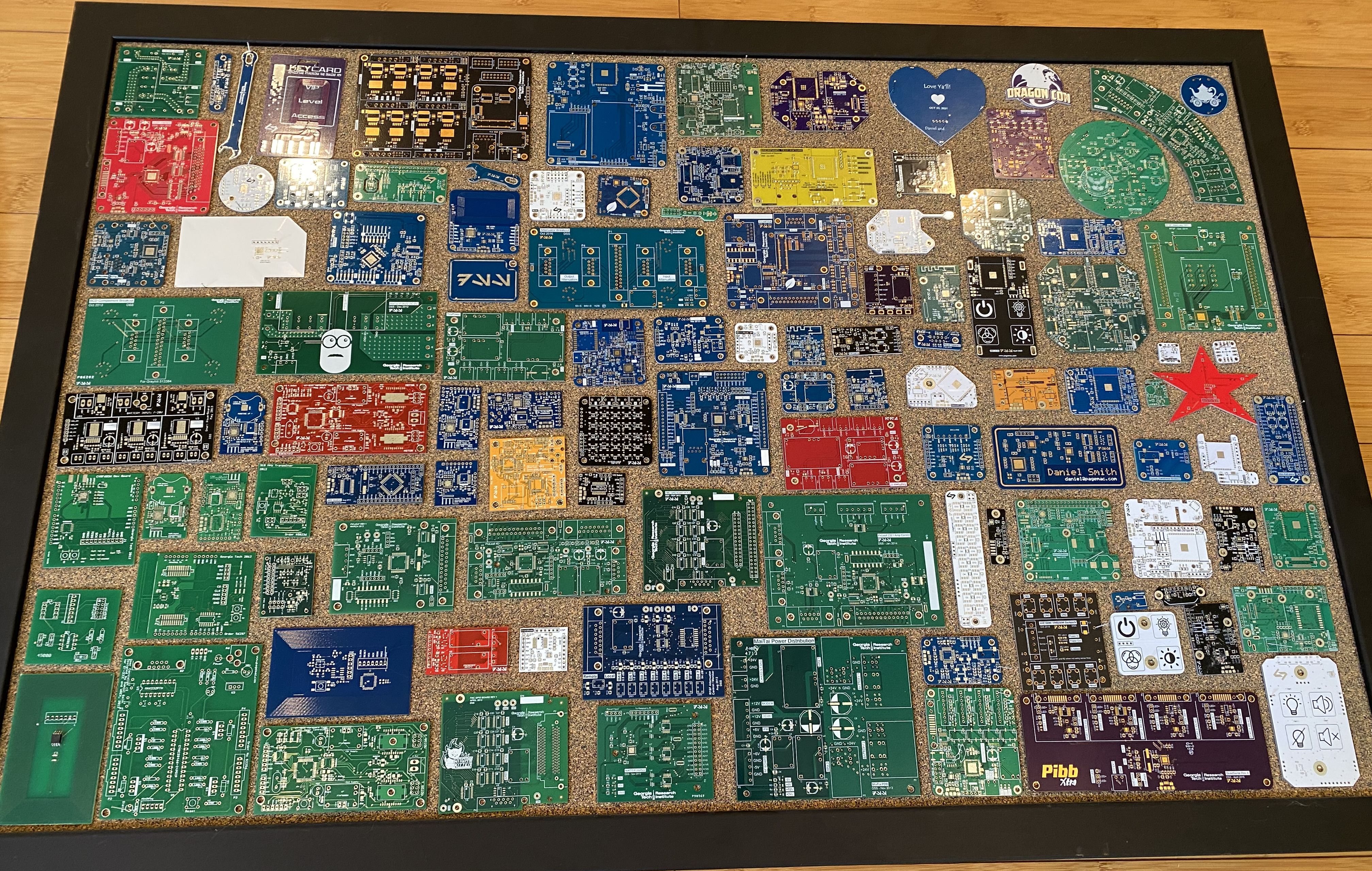
I made my first PCB in 2012 when I was still in grad school. The PCB was designed to be a clone of an RFID card. Shortly after that I made a small adapter PCB to use a BusPirate to program the cards. You can see these in the bottom left of the picture.
My first “real design” (as I felt, at least) was the DoorProgrammer. The project was to allow access control for one of the old WREK studios. It was my first project where I designed the PCB, assembled the board, wrote and programmed the firmware, and wrote the software to communicate with it.
Page Tools
