Sidebar
Table of Contents
LED_Panel

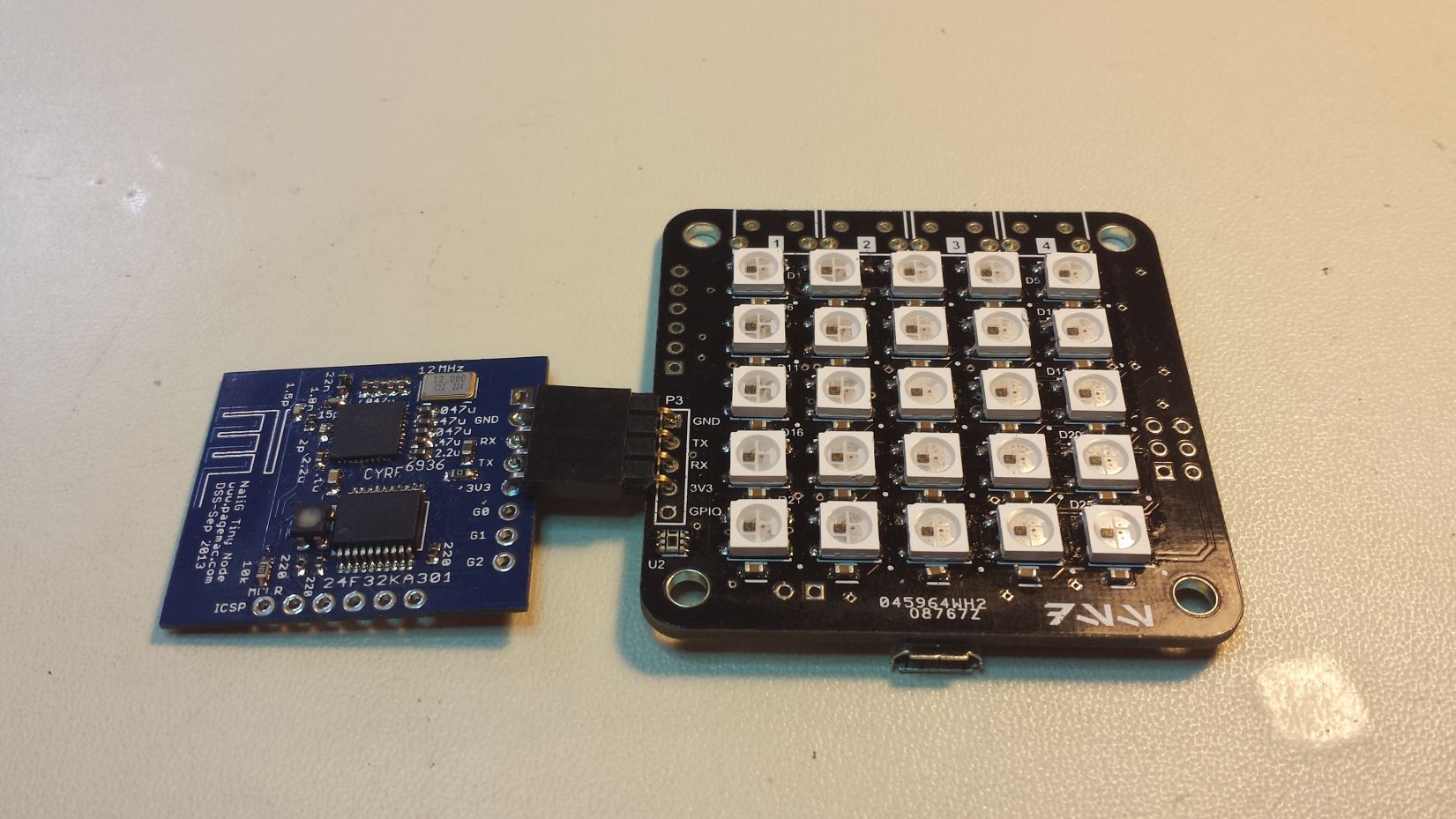
The LED_Panel is PCB with 25 RGB LED's an an ATmega328P microcontroller designed to make cool animations and lighting features for my Apartment Security System. I built this board because I started learning about the WS2812 RGB LED's with integrated controllers. This means you can set the LEDs to any 24 bit color (8 bits for all 3 red, green and blue channels), and they maintain their color until programmed with the next color. The best part is the LEDs are controlled with a single data line from the microcontroller and daisy-chained to as many LEDs as you want.
There's already plenty of PCB's in various shapes with any number of these WS2812 LED's, but I wanted to build my own board that had its own microcontroller on the PCB so the board can operate as an independent module. So I built the LED_Panel!
Hardware Design
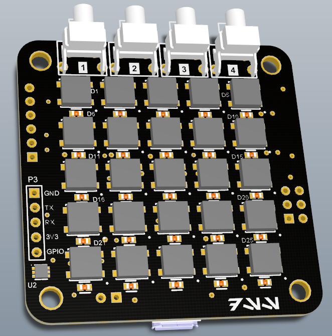
I wanted to make this board with one of my usual Chinese board manufacturers, and to keep it cheap, the board had to be less than 5x5cm. I figured I could comfortably fit a 5×5 grid of RGB LED's in this space, while still leaving enough room for some buttons and mounting holes. I decided to make this board compatible with Dangerous Prototype's Sick of Beige line of acrylic cases.
At the time I was designing the board, I had the option of choosing the WS2812 or the WS2812B. I chose the WS2812B because it had a better pinout that made laying out the board easier. The WS2812 has 6 pins and the WS2812B has four pins. The extra two pins on the WS2812 are No Connect and an extra power input, plus it has the data input and data output pins on the same side of the package. The WS2812B has the data input and data output pins on the opposite side of the package - this makes it much easier to layout 25 LED's on a 2-layer board!
Controlling the LED's requires a somewhat convoluted 1-wire protocol with strict timing. Unfortunately this somewhat limits microcontroller selection options, so for convenience I decided to make this board powered by Arduino. Adafruit already wrote an Arduino library for the the WS2812, so I decided to just use that instead of implementing the protocol on a PIC. Just like with my serialMP3 project, I bought regular ATmega328P microcontrollers and programmed them with the Arduino bootloader.
On the front of the board, there is a spot for 4 right-angle pushbuttons. I wasn't sure what I'd end up using them for, but I'm glad I added them. I currently use the buttons as a sort of menu system to send commands to the security system.
Additionally, I added a ISL76671 light sensor, which is the same sensor used on the EnviroNode. I wanted to be able to “auto-dim” the brightness of the LED's based on the brightness of the room. This ended up being a really cool feature.
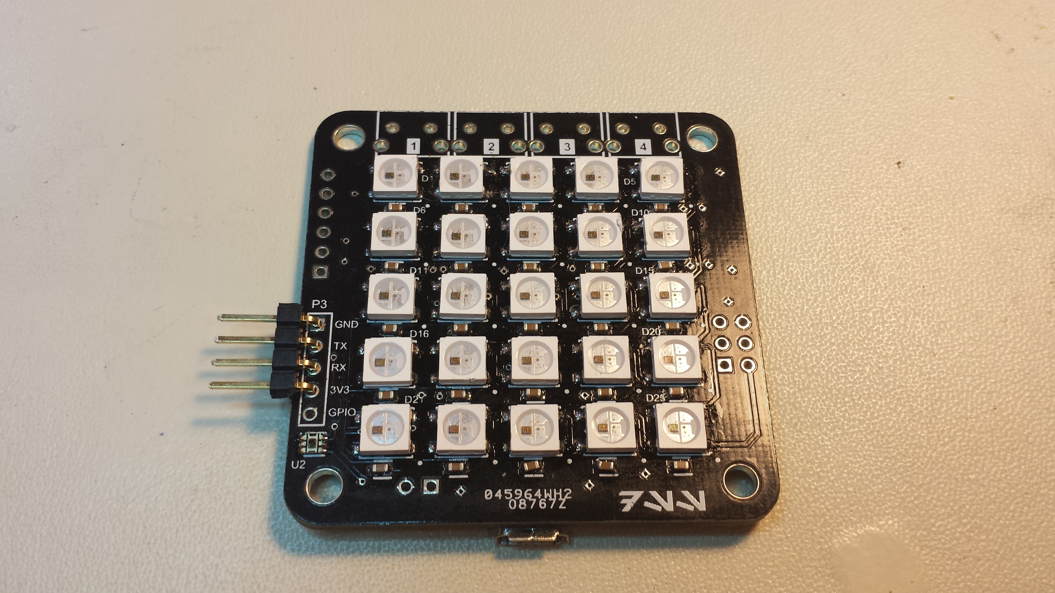
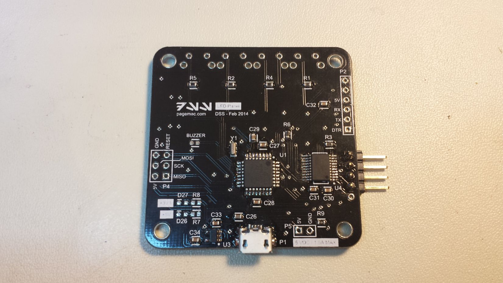
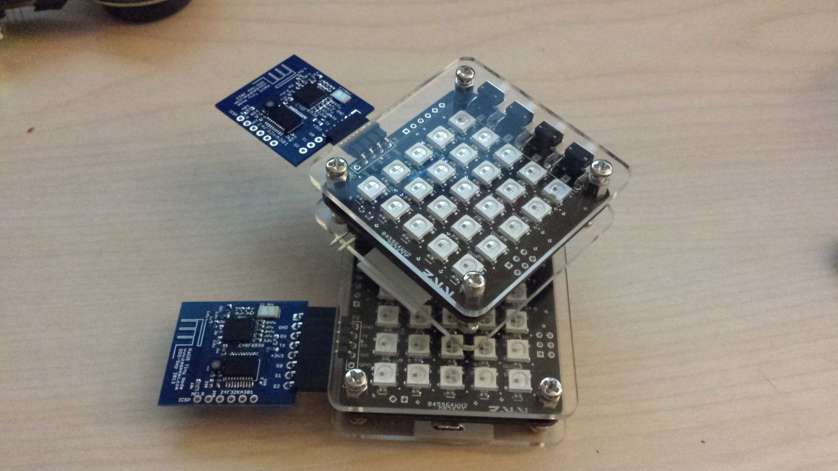
There are 4 connectors on the board. P2 is a connector for a wireless module and has serial TX, RX, a GPIO pin and power. P3 is an FTDI connector for programming Arduino code onto the device. P4 is the ICSP port for loading the Arduino bootloader (or optionally for firmware programming).
P1 is a microUSB connector used for 5V power only, no data. The LED's and microcontroller run on 5V, but the wireless module requires 3V. So there's a small LDO to generate 3.3V, as well as a level shifter to translate serial data between the ATmega328 and the wireless module.
Finally, I also left a small header to solder on a piezo speaker so the board can also make beeping sounds!
Firmware
After assembling the board, I first loaded the Arduino bootloader using the same method as with the serialMP3. From there, I began hacking together some “dumb” firmware. As with my other security system modules, the LED_Panel has a simple serial interface which has several commands to run various animations, display images, and play beeping sounds through the piezo speaker.
The basic flow of code allows for a static “image” to be displayed on the screen with a single color. The image is stored as an array of LED indexes that should be turned on to produce that image. The color is determined from the current “status color” of the LED_panel, and the brightness intensity of the LED's is determined by the light sensor. Over a 5 second interval, the LED_Panel will take 5 brightness readings from the light sensor, average the results and determine the correct brightness for the LED's. This allows you to turn lights on and off in a room, and the LED_Panel will respond and adjust it's brightness so that it is always at a comfortable level. In a completely dark room, the LED's will drop to minimum brightness. After you turn a light on, the LED's will brighten up to match the room.
The color and brightness can also be “forced” to stay at a specific color and/or brightness.
Default Behavior
By default, all of the LED's are off. The LED_panel will send a '>?' over serial, and if a wireless module is connected, it will recognize this command as “WHAT AM I??”. The wireless module will relay the message to the master node, which will send a message to the LED_Panel with the correct image and color to display.
After that, the security system will send various commands based on system state. For example, door open/close animations, updating the system status, countdown until the system is armed, etc.
Buttons and Codes
There are four buttons on the LED_Panel. In the default mode, these buttons are used to enter a 5 digit code (of course, you can only use the digits 1 through 4). As you enter buttons, the middle row of LED's will turn purple and indicate how many buttons you've pressed. If you don't enter 5 digits within a few seconds, the panel will show a red X and reset “buttons pressed” bar. If you enter all 5 digits, the LED_Panel will send a serial message to the master node and reset. If the master node isn't listening or no wireless mode is connected, nothing else will happen.
If there is a maser node, it will then interpret the code and send various responses. An invalid code will get a red X, a valid code might get an unlock animation or a check mark.
Eventually I'll build a real panel with a touchscreen that can provide better feedback for the security system, but for now, it's fun to play with!
Demo Mode
If you hold down button 1 while powering the device on, the LED_Panel goes into “demo mode”. This is a fun mode used to demonstrate the capabilities of the LED_panel - using the buttons on the top, you can cycle through the various animation modes, change the colors and pictures.
Animations and Effects
The LED_Panel has a variety of animation and picture modes that can be activated from the serial link.
Commands include:
- Display a static image (can also specify color and static brightness)
- Display one-time animation, such as “unlock” or “invalid command red X” (includes beeps)
- Display continuous animation, such as ticking clock, moving arrows or a wireless symbol
- Blink all the LED's rapidly in what I call “police mode” (it looks like police lights when it flashes between red and blue)
- Display an “ambient light mode”, which is just a cool pattern of slowly changing colors.
Security System
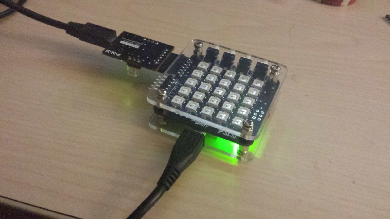
Integration with my security system was the main goal for building the LED_Panel. I basically had two uses for this board: ambient lighting and control panels by some doors. The ambient lighting modules generally don't have the buttons installed, don't have cases, and are used either in some kind of light fixture or in other places like over my kitchen sink. The control panel boards have the buttons installed and are inside Sick of Beige cases.
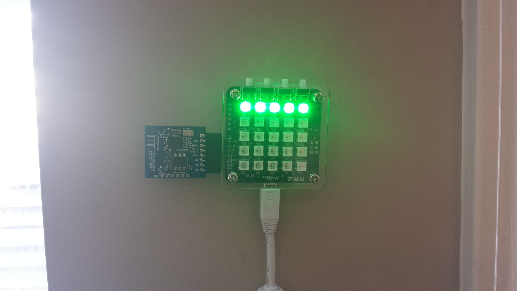
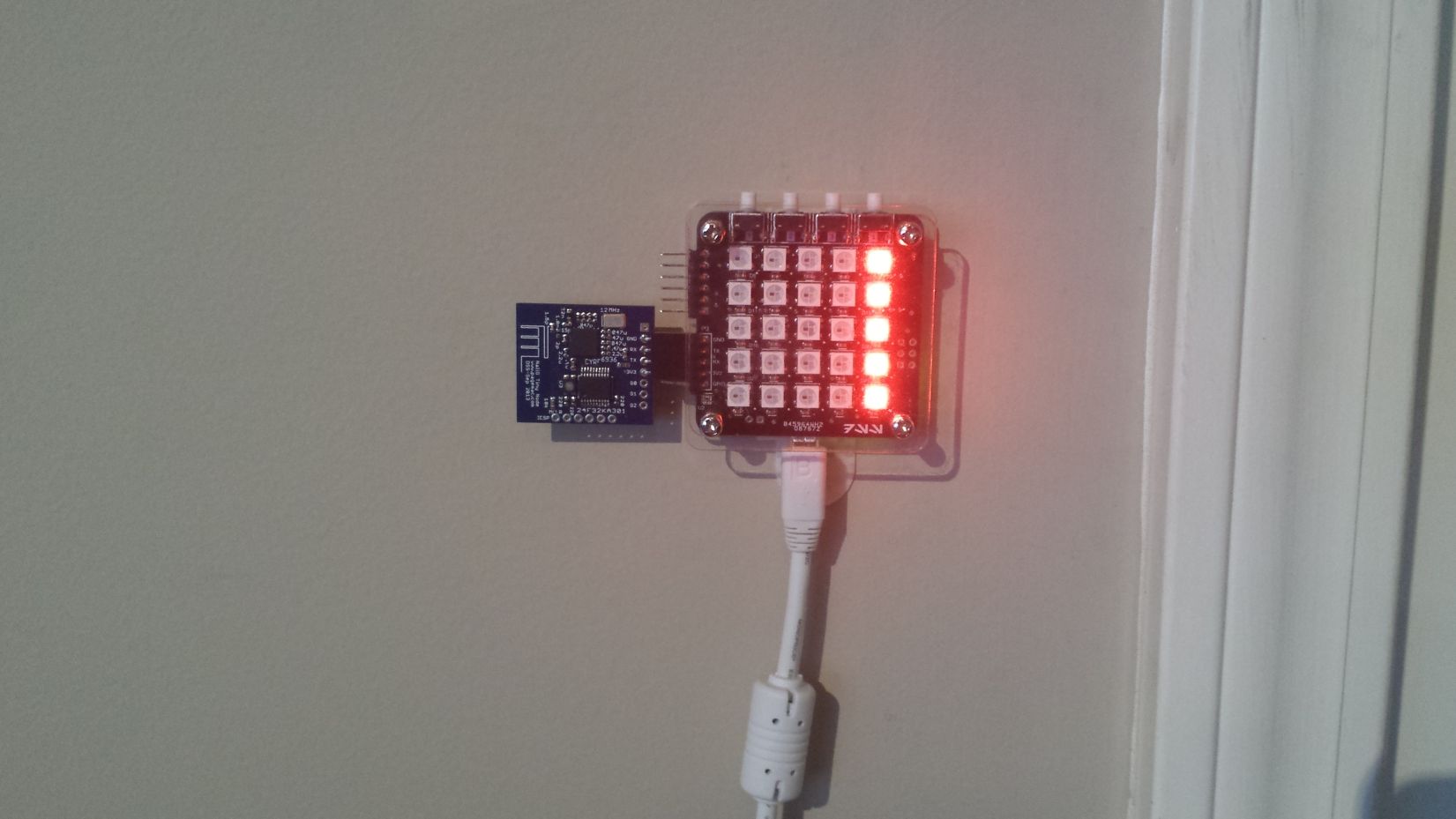
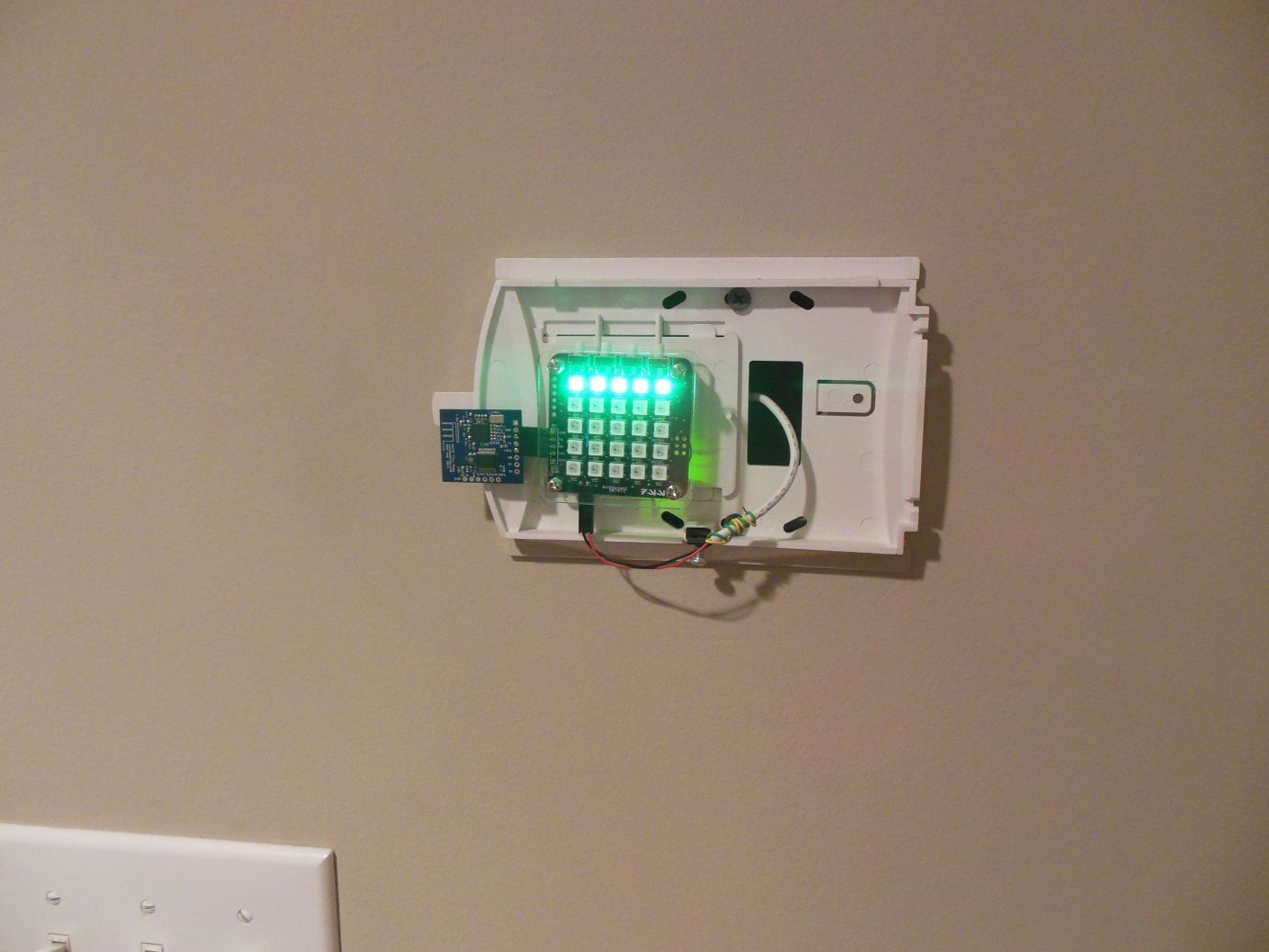
I have control panels on 3 doors; 2 exterior doors and 1 interior closet. The exterior doors have a green horizontal bar on the top of the panel when the system is disarmed. When the system is armed, the bar turns red. The interior closet door has a vertical bar on the right (same side as the door) which is red when the door is normally locked. When the door is unlocked, the bar turns green. It turns red again as the door locks.
Read more about how these panels are integrated into my security system!
Downloads
PCB: Feb 2014
Writeup: July 2015
Page Tools
