Sidebar
Table of Contents
Reverse Engineering a Doorking Transmitter
My apartment complex uses these keyfobs, a Doorking MicroCLIK Proxmitter, for access into the building and the garage. We also use a Monarch 318DOPW1K by Transmitter Solutions (pictured below), which is supposed to be functionally identical to the Doorking model. The Monarch is the model we analyzed. The keyfob has two components: an active transmitter for access in to the garage for your car, and a passive RFID card to get into the building. The RFID card is just a HID Proximity card, and I can already emulate those with an AVRFID tag. However, my friend Kevin and I wanted to reverse engineer the active transmitter so that we could make additional transmitters and build them into our cars.
These transmitters use fixed codes, NOT rolling codes. DoorKing does have a product line that use the Keeloq rolling codes.

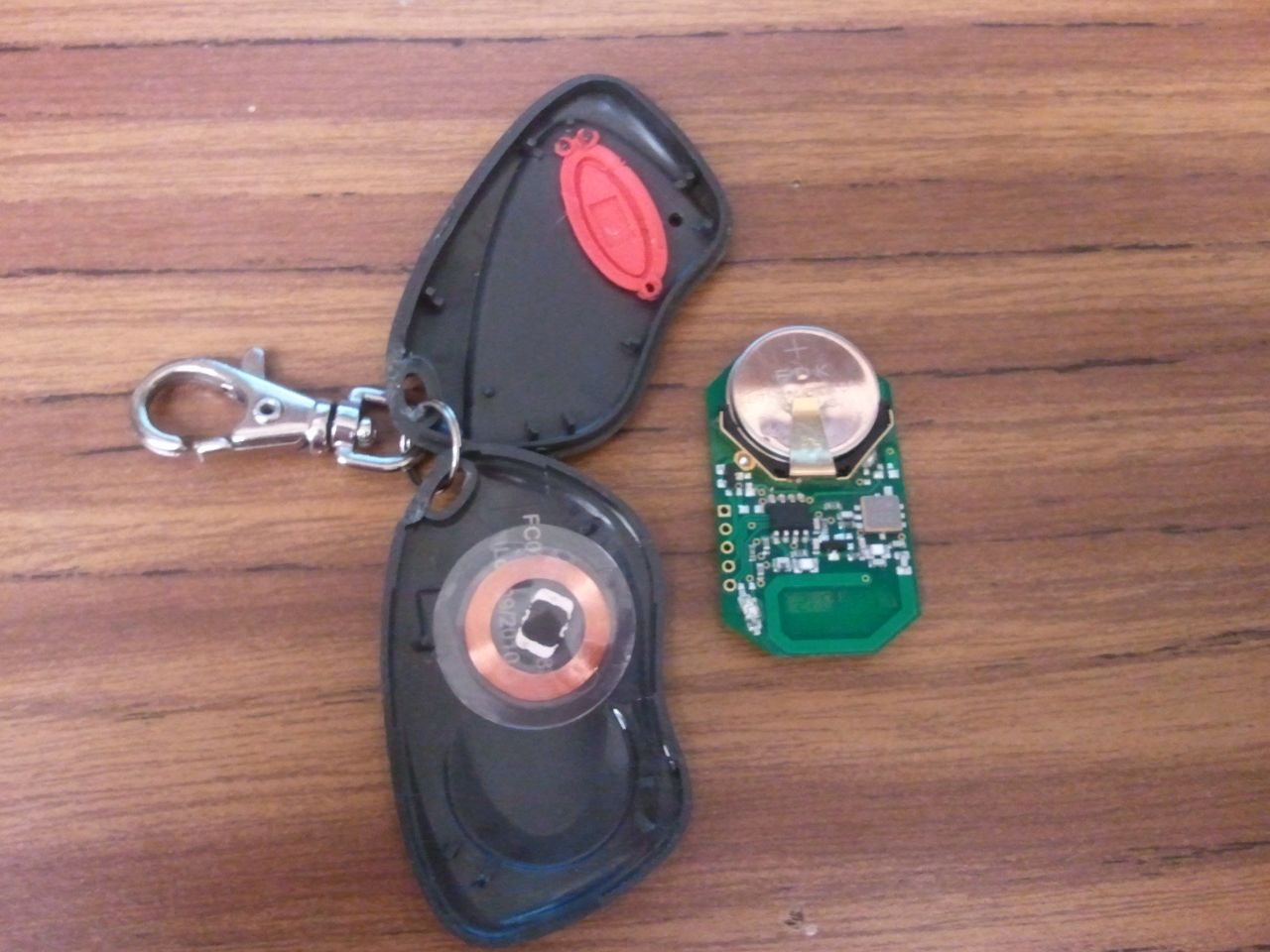
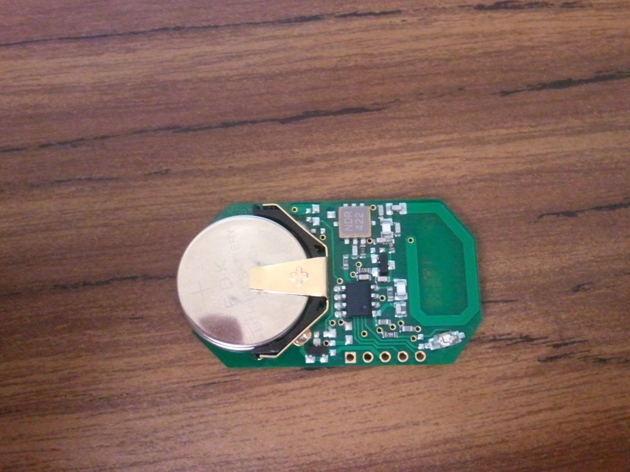
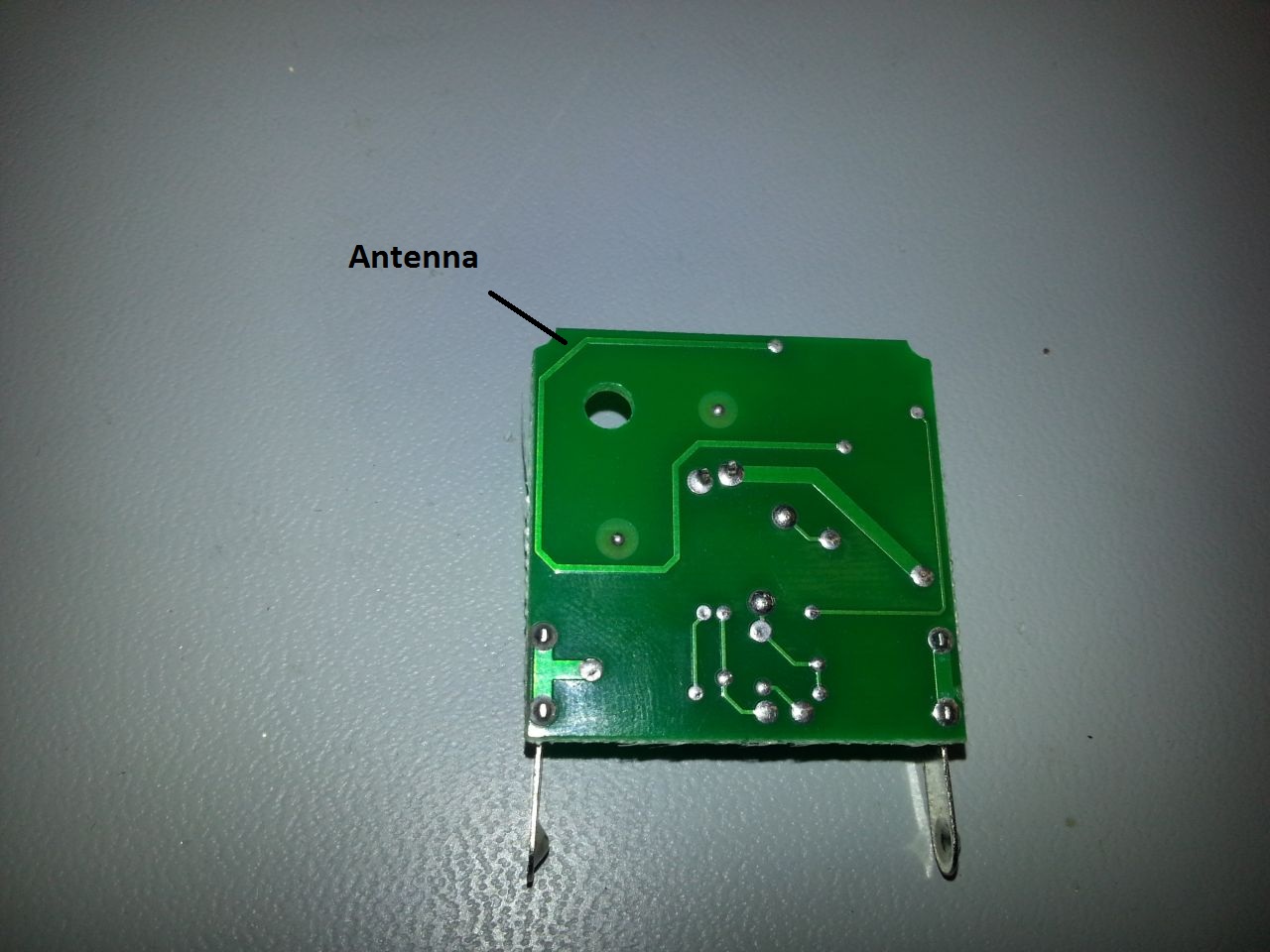
We cracked open the shall of the keyfob and found that there are two parts, the PCB for the transmitter and a separate coil and tag for the proximity card. The board consisted of a battery, protection diode, PIC micrcontroller, LED, button, SAW resonator, transistor, a bunch of passive components and a PCB antenna. The first thing I did was trace out the schematic using a multimeter:
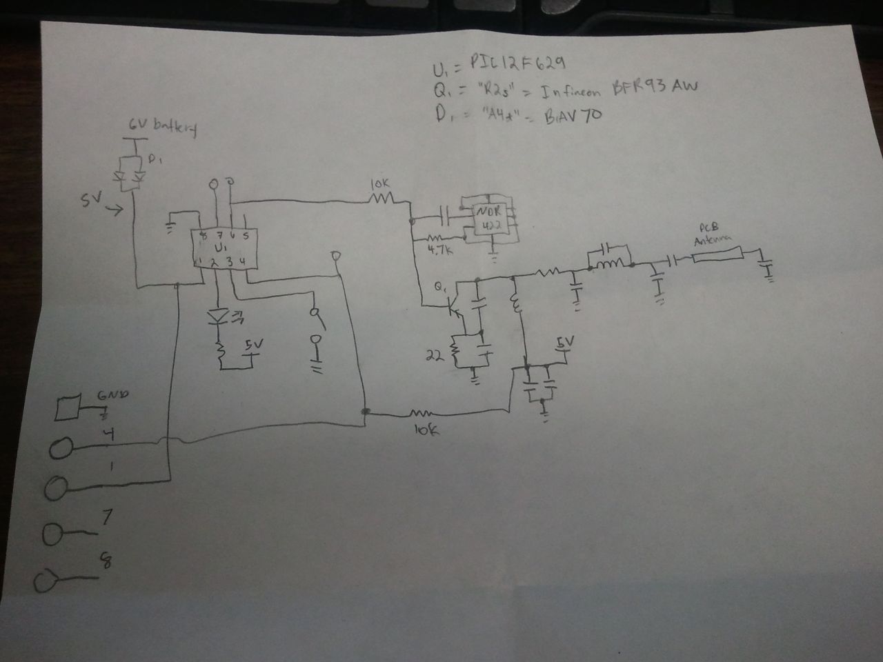
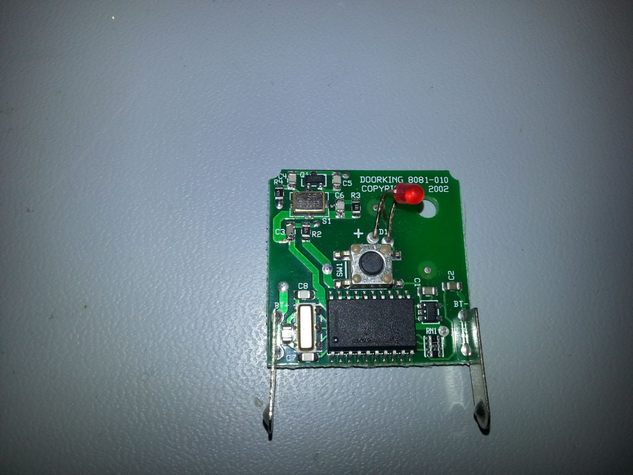
We also took apart an original DoorKing Transmitter. It was later found to have used the reference schematic as found in the SAW resonator datasheet.
Digital Circuit
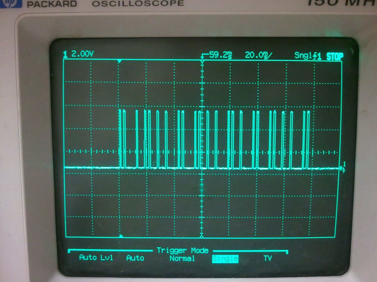
Scoping the output of the PIC revealed a very simple digital output. When the button was pressed, the PIC would output a series of 5V pulses. Each pulse was 1ms long, followed by a gap of either 2ms or 5ms. We realized it was simple timing: sample the signal every 3ms from the first pulse to get the bit data. If it's high, it's a 1. If it's low, it's a 0.
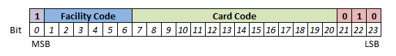
At this point we got an actual binary bit stream. We got a total of 48 bits, but they were manchester encoded, so after decoding we had 24 bits. Since we already knew that we were looking for a facility code and card code (they are printed on the back of the keyfob), we knew what bits to look for. Although I was expecting the 26 bit format, it turns out they used a modified format with the first 6 bits as the facility code and the next 14 bits as the card code. There's also a 1-bit start bit (to indicate “start of data”) and a 3-bit stop sequence, which were always 010 as far as we could tell. We confirmed this format consistancy with several other keyfobs. Below is a diagram of the bit sequence.
RF Circuit: SAW Transmiter
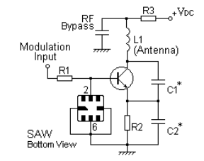
The digital pulses were sent in to a crystal and a transistor. The crystal was a NDR 422, which is actually a SAW (surface acoustic wave) resonator. This crystal oscillates at 318 MHz. The digital pulses were modulating the resonator, turning it on and off, making it a very simple ASK transmitter. Actually, it's really On-Off Keying (OOK), a subset of ASK, since the transmitter output is either “on” or “off”. The datasheet contained a schematic for a simple transmitter design.
This schematic differs greatly from the keyfobs that we have. I decided to take apart an original DoorKing transmitter, and found that it's schematic matches the above schematic.
It turns out that making this SAW transmitter work was pretty tough. We made 3 prototypes on the milling machine. The first worked in the lab with our test receiver, but wouldn't open the gates at our garages. The second didn't work at all, and the 3rd behaved similar to the first, although it didn't consistantly work. Each had a slightly different layout, either based on the above schematic or the schematic that we reverse engineered (at the top).
On RFM's website, we found an application note for designing SAW transmitters. This schematic was the same as that in the datasheet for the SAW resonator. Although it gives a range of values, it doesn't really go into detail about how to select values. It does mention that C1, C2 and L1 (the antenna) were key elements in the design. It turns out these elements form a Colpitts oscillator.
I decided to call RFM's tech support and see if they had any ideas. Once I explained what I was doing, the engineer immediately knew what to tell me. He said to replace the SAW resonator with a 100pf capacitor, then get the Colpitts oscillator working within 1MHz of the target frequency. The ratio of C1 to C2 should be between 1 to 3 to 1 to 5. Put the resonator back on and the transmitter should work. So we did just that. We used the suggested values for all other components. After trial and error, we found that we could leave C1 open (the board capacitance was enough) and C2 was 4.7pF. The resonator seemed to work great! We tested with an oscilloscope and spectrum analyzer. This design process would have to be repeated on every different board layout.
Prototype Transmitters
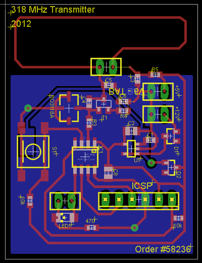
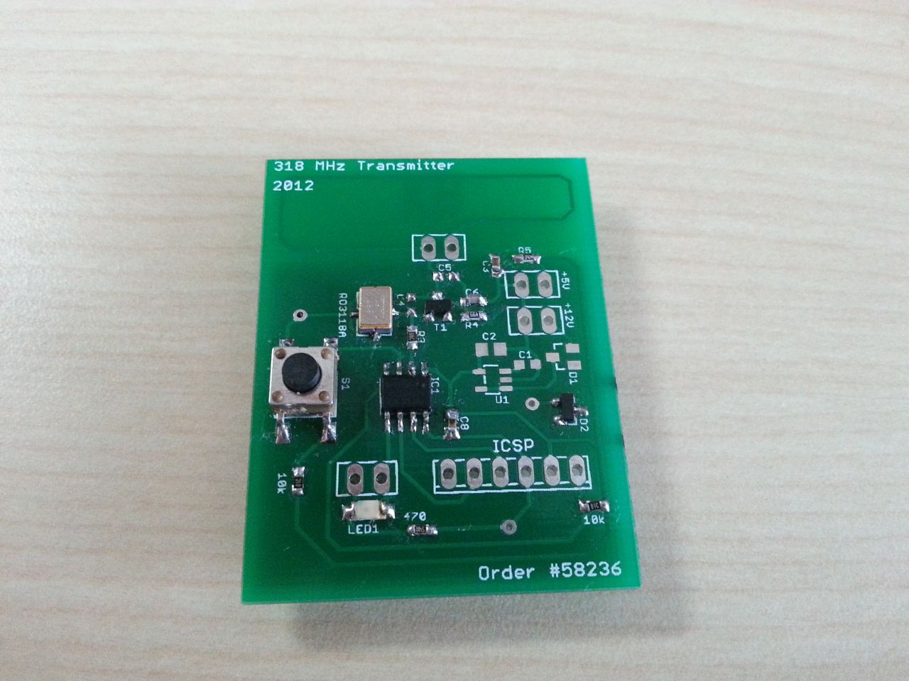
We milled our first prototype using the keyfob and SAW resonator datasheet as reference. We couldn't actually find anywhere to source an NDR 422, so we selected another SAW resonator, the RO3118A. The full schematic and BOM is at the bottom of this page.
Writing the PIC source code was fairly easy. It just uses a timer to measure the 1ms and 2ms gaps and toggles a pin. We used a PIC12F629, the same PIC as the Monarch transmitter.


The 4th prototype was fabricated at Seeed Studio. This was the only board where we actually implemented the Colpitts oscillator correctly using the procedure described above. The board is actually not the best design - the application note says that the grounds for the resonator should be very close to that of C2 and C3. The grounds aren't close on our transmitter, but we were still able to get the resonator to work. The board can be powered with 2 CR2016 20mm coin cell batteries or with a voltage regulator, which is for integration with vehicles.
Unfortunately, it still didn't work. The 318 MHz resonator worked, the PIC was outputting the correct data with the correct timing, and the board worked in our lab. Yet we still couldn't get it to open the garage door. I even checked the output on a spectrum analyzer to verify that the power levels were similar to the original keyfob and that there were no other noise sources.
Out of desperation, I tried to connect the output of the original transmitter's microcontroller to our prototype's SAW transmitter. It opened the gate! Eventually we realize our mistake - it was the timing BETWEEN the sequences. The original transmitter had a 15 ms gap between seqeunces while our transmitter had 20 ms. We originally thought this would not matter since it's just repeating the same sequence, but the receiver must be expecting to hear the same code at least twice within a certain time frame as a form of error correction. Our transmitters now work very well!

Test Receiver
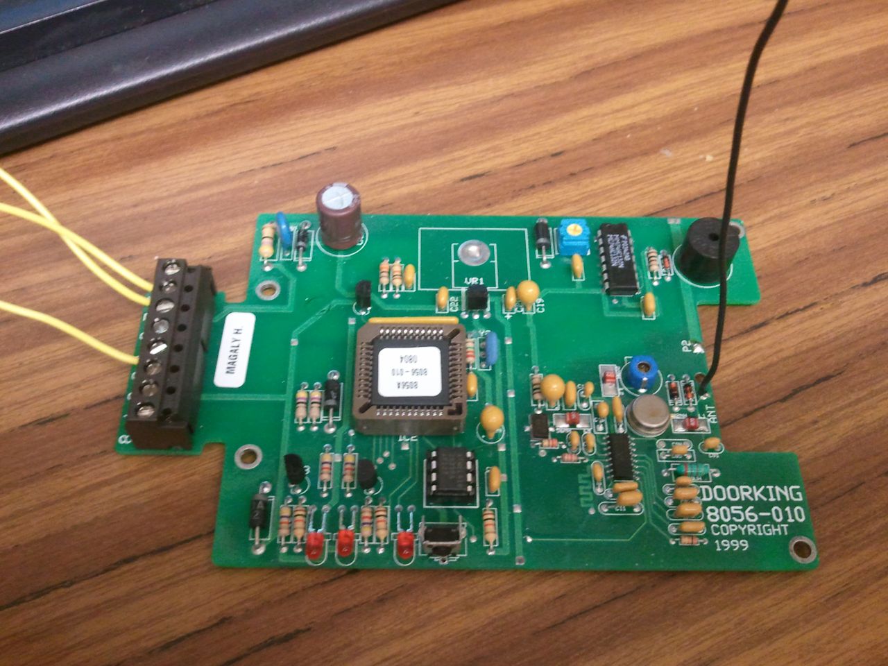
We had no real way to test the transmitter other than trying it at the apartment garage. I decided to search eBay, and found a Doorking 8056 reader for a reasonable price. I powered it up and tried activating my keyfob. Although a little LED lit up, there was no data output. I realized that the 8056 is actually for Doorking's “more secure” version of these transmitters, the microPLUS.
Not a problem! The receiver board layout is has very distinct sections for the microcontroller and the RF front end. In fact, other than power and ground, there was just one trace linking the two sections of the board. That data trace was the ASK decoded bits. We decided we could just use our own microcontroller to decode those bits and make our own reader.
We used a PSoC from Cypress to do the decoding. The bare ASK receiver was extremely sensitive, it was constantly outputting noise bits. The only way to find real data is looking for a string of Manchester encoded bits. (In Manchester encoding, a 1 is represented as a 01 and a 0 is represented as a 10. So you can never have three repeating bits). Any other data is dropped.

The receiver worked great for testing. It has no problem decoding data from our original keyfobs. This also helped us test our prototype transmitter. Unfortunately, the unit was disassembled after testing (we needed the PSoC dev board for something else). This is probably something I can do with an SDR in the future anyways.
Downloads
Page Tools
