Sidebar
Table of Contents
AVRFID PCB Implementation
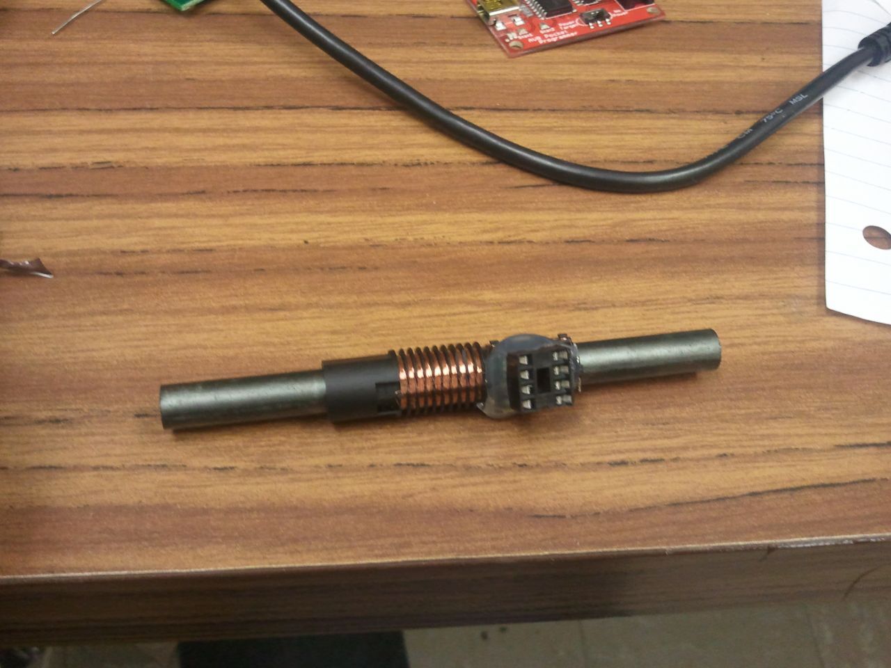
One day I came across a software-only implementation of a passive low-frequency RFID tag using an AVR microcontroller. Micah’s AVRFID project was a very unique implementation of RFID, and I was specifically interested in its ability to emulate HID cards. Although I've used plenty of other microcontrollers, this was my first time playing with an AVR. Fortunately, I had recently purchased a BusPirate (which is the coolest thing) and it's capable of programming AVR's. I set everything up on a proto board and was able to get a simple RFID tag working with just the AVR and a coil of wire.
Bit Format Issue
Since I had some knowledge of RFID bit formats, I noticed that the bit formatting was wrong. She got the facility code, card code and odd parity, but she mixed the even parity in with the manufacturer code. (I speculate that she didn't notice the error because a lot of access controllers don't look at parity bits). The manufacturer code actually has important header information in that it determines how many bits are transmitted. While all of these cards are transmitting 45 bits over RF, the number of bits outputted by the reader are determined by that header.
By trial and error, a friend and I determined the correct header for the 35 bit format. I also re-wrote all of the parity macros so that they generate the correct parities for the 26 bit and 35 bit formats. This part was a little more tricky because there's not a lot of information on the HID 35 bit format. More formats could easily be added.
You can download my revision of the AVRFID code here at the bottom of this page.
Building Better Cards
Having a coil of wire and a small chip that act like a card is pretty cool, but I wanted something that worked a little better. The first thing I tried was attaching the AVR's to coils from some other RFID tags. I had a bunch of TI tags that I sampled a while back, and they operated on 134 kHz so the coils were about the right inductance.

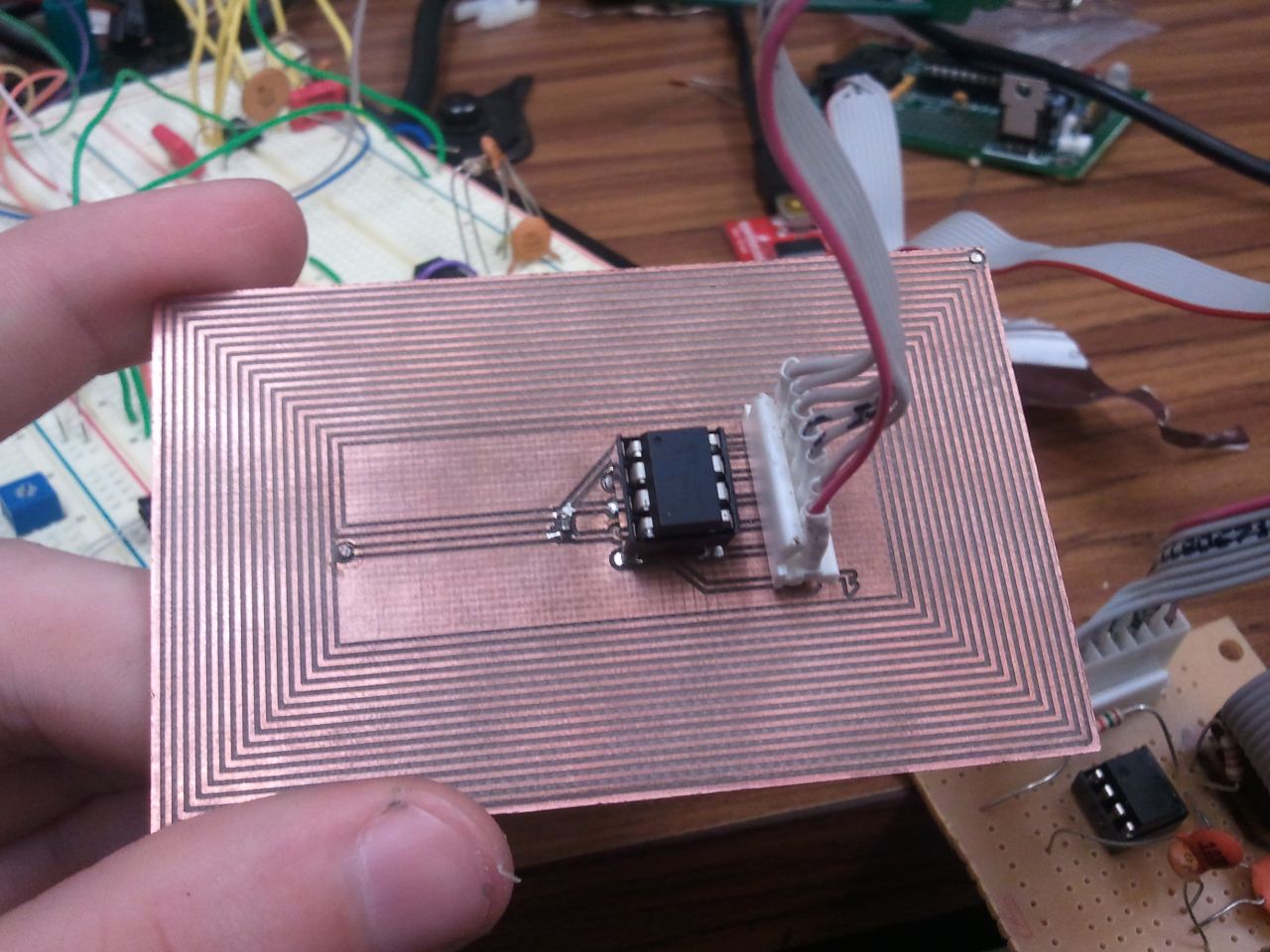
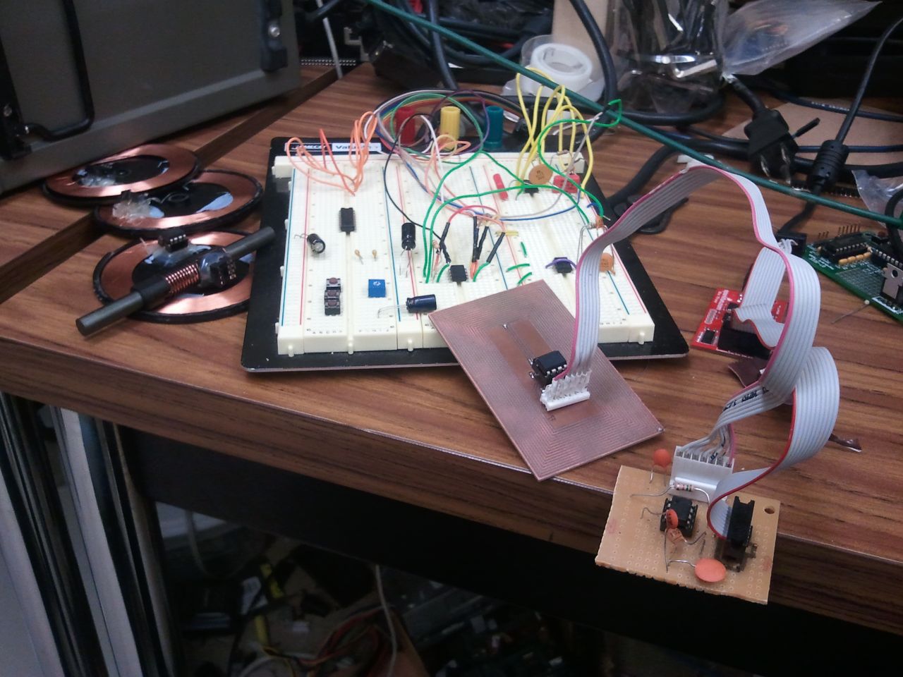
These tags worked pretty well, but their range was less than an actual card. I was able to tune them with a capacitor to make it a proper LC tank circuit, but that only helped a little. I figured I could make a PCB that would do the job and allow me to add tuning capacitors. The first prototype is on the right in the above images. It has a simple programming header that connects to a small board which connects to the BusPirate. It only has 14 loops per side. The card worked pretty well, but I thought I could do better!
PCB for AVRFID
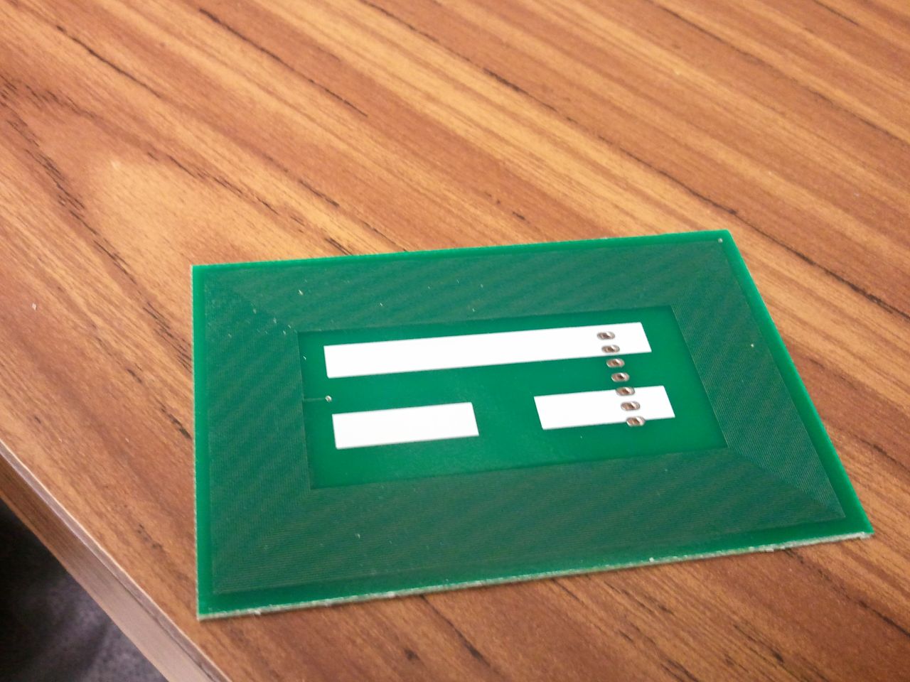
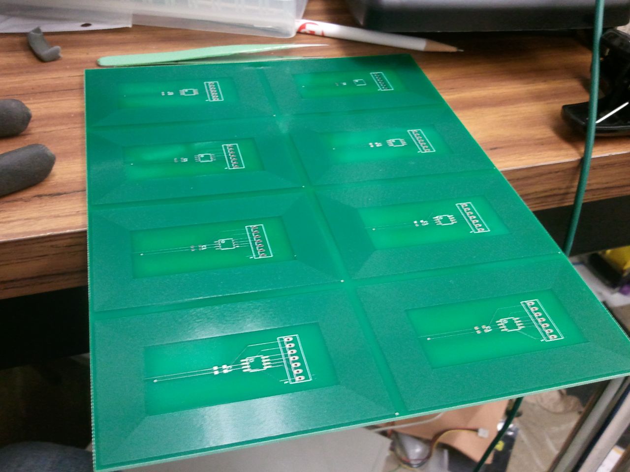
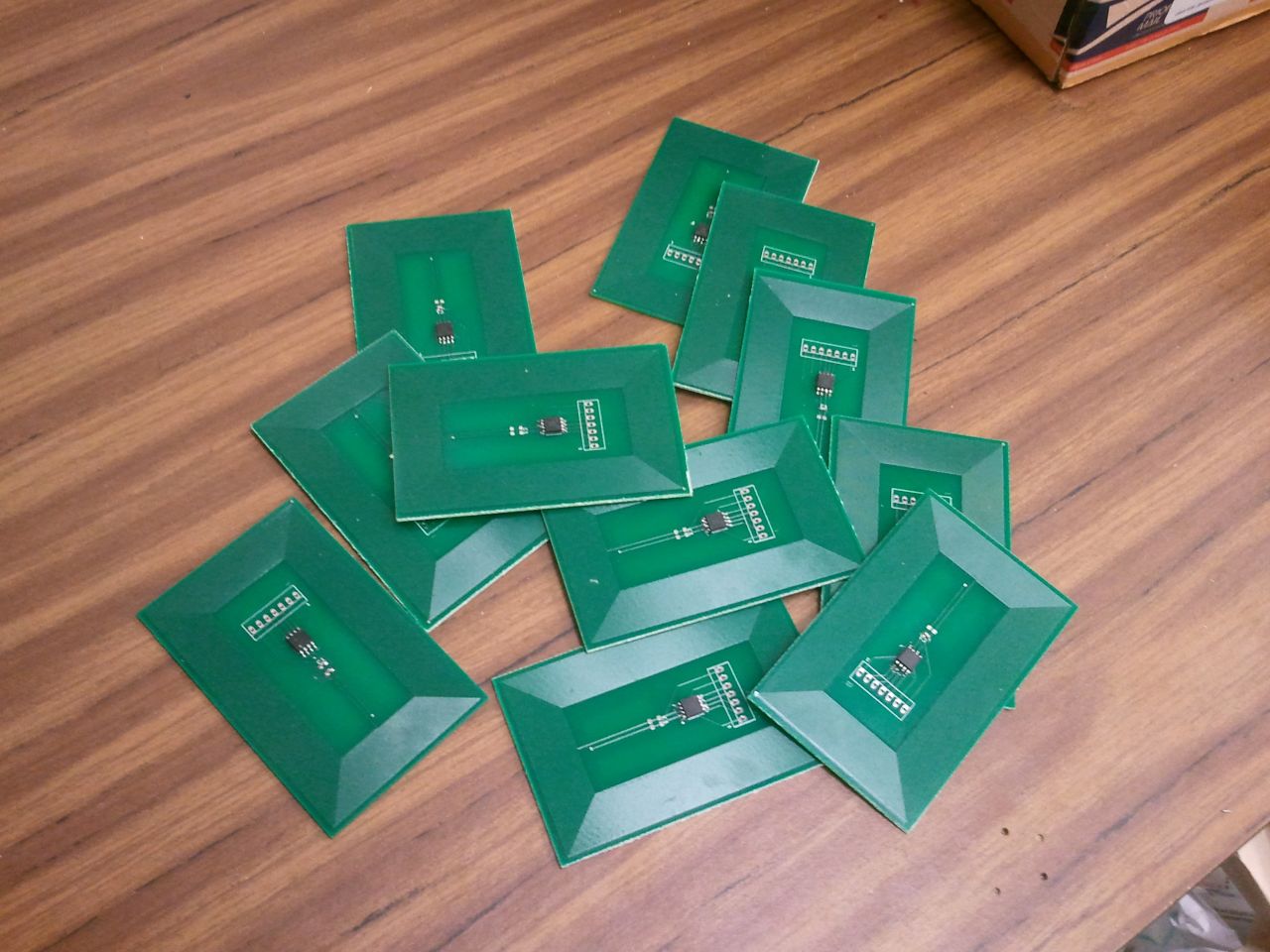
I designed the PCB with the same dimensions as a credit card so I could put it in my wallet easily. This card has 43 loops per side (more loops = more induced current = works at a better range, roughly). The loops are tiny 6 mil traces with 6 mil spacing, the smallest I could make them. The only component required for the board was the surface mount AVR, but there were also pads for tuning capacitors.

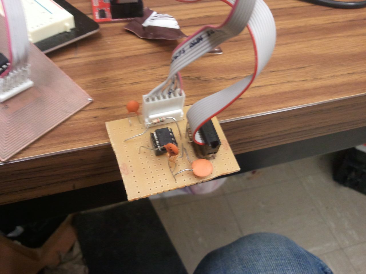
The programming header connects to a custom programming board I made. The programming board connects most signals straight to the BusPirate, but it also has a 555 timer on it for clock generation. An external clock is required to program these chips (since during normal operation, the AVR's clock is coming from the RFID reader), so that's why I used the 555 timer. However, there are probably some better AVR programmers out there that can do this already; I was just working with what I have.
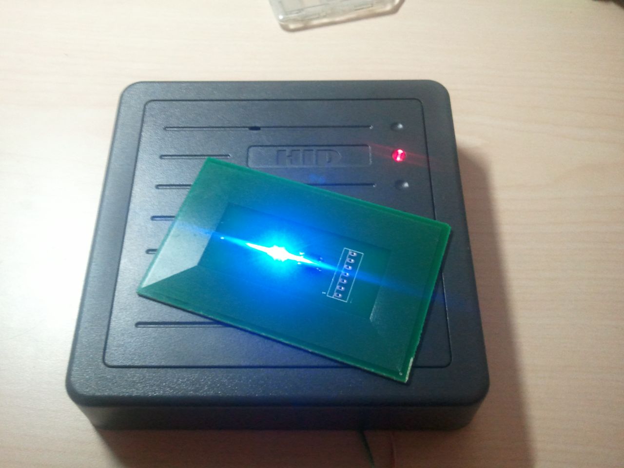
The boards worked well and could be read from a further distance than my other tags, plus they looked a lot cooler. There was one problem though. I found that when I got the PCB cards too close to a reader, they wouldn't work. You could move it slowly in front of the reader and it work, but place it quickly right to the front and it would not.
After some debugging, I found that the voltage on the PCB coil was getting up to 10V when the PCB card was placed directly on the reader. The max voltage for the AVR is 6.5V, so that explains it. The best way to reduce this voltage turned out to be a pair of blue LED's. Blue LED's have a voltage drop of about 3.5V (as opposed to red LED's which have about a 1.5V drop) which allows the PCB cards to work at a close range. I found some cheap 0603 blue LED's and put them on the cards with great success. Turns out the tuning capacitors weren't really needed either. Plus the LED's blink when you put it in the field of a reader!
Programming Header Pinout
The PCB has the following pinout. Before I built the custom programmer, I just used my BusPirate and a function generator.
- Pin 1 - Ground
- Pin 2 - MOSI
- Pin 3 - MISO
- Pin 4 - SCK
- Pin 5 - VCC
- Pin 6 - RESET
- Pin 7 - EXT_CLOCK (anything over 200 kHz from a function generator)
Programming with avrdude
The fuse on the AVR has to be configured so that the microcontroller uses an external clock source (which is the carrier of the RFID reader). This command configures the fuse with a BusPirate:
avrdude -p t85 -c buspirate -v -U lfuse:w:0xC0:m
This command programs the AVR using the BusPirate:
avrdude -p t85 -c buspirate -V -U flash:w:avrfid.hex
Note that there is a newer version of avrdude that will program the AVR much faster compared to the version provided with WinAVR. I used avrdude version 5.10svn.
Downloads
Page Tools
