Table of Contents
Door Controller
The goal of this project was to create a small, cheap controller that would allow electronic access to up to 4 doors. Each door would have an HID RFID reader (125kHz Prox Cards) and 12V electronic strike and would be connected to the controller via an 8-conductor Cat-5 cable. The controller should be able to operate and authorize cards independently with its own flash memory, though a computer can be used for programming and optionally authentication and logging. The target installation was at WREK Radio, which would also have additional integration software to allow control of the Door Controller through the station's web interface.
The hardware, firmware and software was used at WREK from 2012 to 2015.
History
For many years, I wanted to add RFID access to all of the doors at the WREK radio station. All students already had a student ID with RFID prox technology, and I had already figured out how to interface with the RFID readers and decode the data. And I had already built a kiosk that controlled one door at the IEEE hardware lab, so why not four? I just needed a device that had four ports, and each port could connect to an RFID reader and electric door strike.
I made the first proof-of-concept with a PIC18F4620. I modified code from the lab kiosk so that it could handle four doors. This was tricky, because my code required two hardware pin interrupts for one reader. Unfortunately, the PIC I was using only had 3 interrupt pins available, so I tried using the PIC's PORTB interrupt-on-change. The difference was instead of the interrupt routine knowing exactly which pin changed with the pin interrupt, the interrupt-on-change did not so you have to read the pin values. This was too slow, so I used some JK Flip-Flops save the state. Although this worked, I didn't want to use the flip-flops.
I started playing with a small dev board for Cypress's Programmable System-on-Chip, and realized that I could have an interrupt on any pin with this device. I made a second proof-of-concept with the PSoC development board, and it worked quite well. I decided to use the PSoC since the design would require less components.
First Prototype
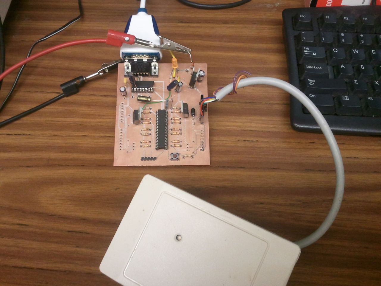
I made the first prototype on a milling machine. It took me a few days to get the prototype working because I had some difficulty getting all the parts on and kept lifting pads (it's very easy to do when you have no solder mask). After several green wire fixes, the prototype worked! I was able to connect 4 readers to the board and it would decode each card and send the data over serial.
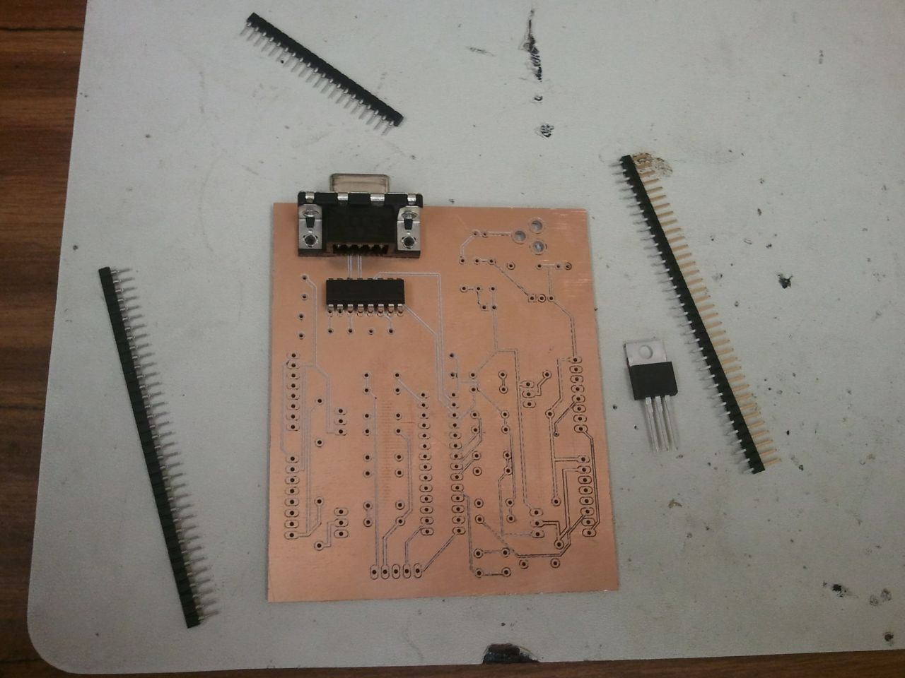

After some more testing, I made a few changes to the schematic and layout, then sent the board off to be made. I got the board made at Seeed Studio, where I was able to order 10 boards for the unbelievable price of $30, including shipping. (they actually ended up sending me 12 boards…). I highly recommend them for personal projects because of the price. It even included silkscreen and soldermask. However, it did take 3 weeks from the time I placed my order to the time it got delivered to me.
Hardware Description
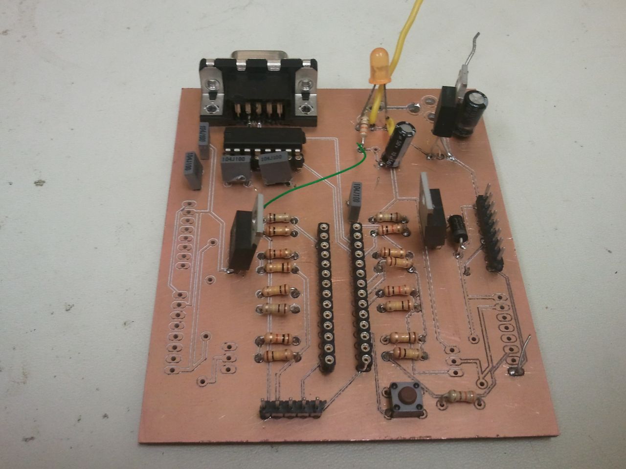
The board has only through-hole components. Although I usually prefer surface mount components, I wanted this to be easily repairable by future station engineers.
The board is designed around a Cypress CY8C29466 PSoC in a 28-pin DIP package. Most of the I/O pins are used on the four door ports. There's a MAX232 level shifter and DB9 port for serial communications - I considered using a USB to serial converter, but I planned to use an actual serial port at the station. There's also a power jack and voltage regulator.
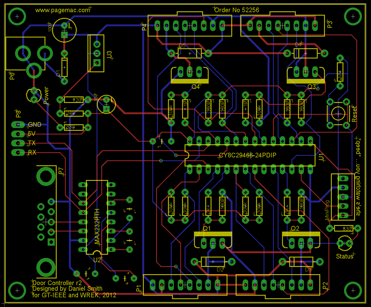

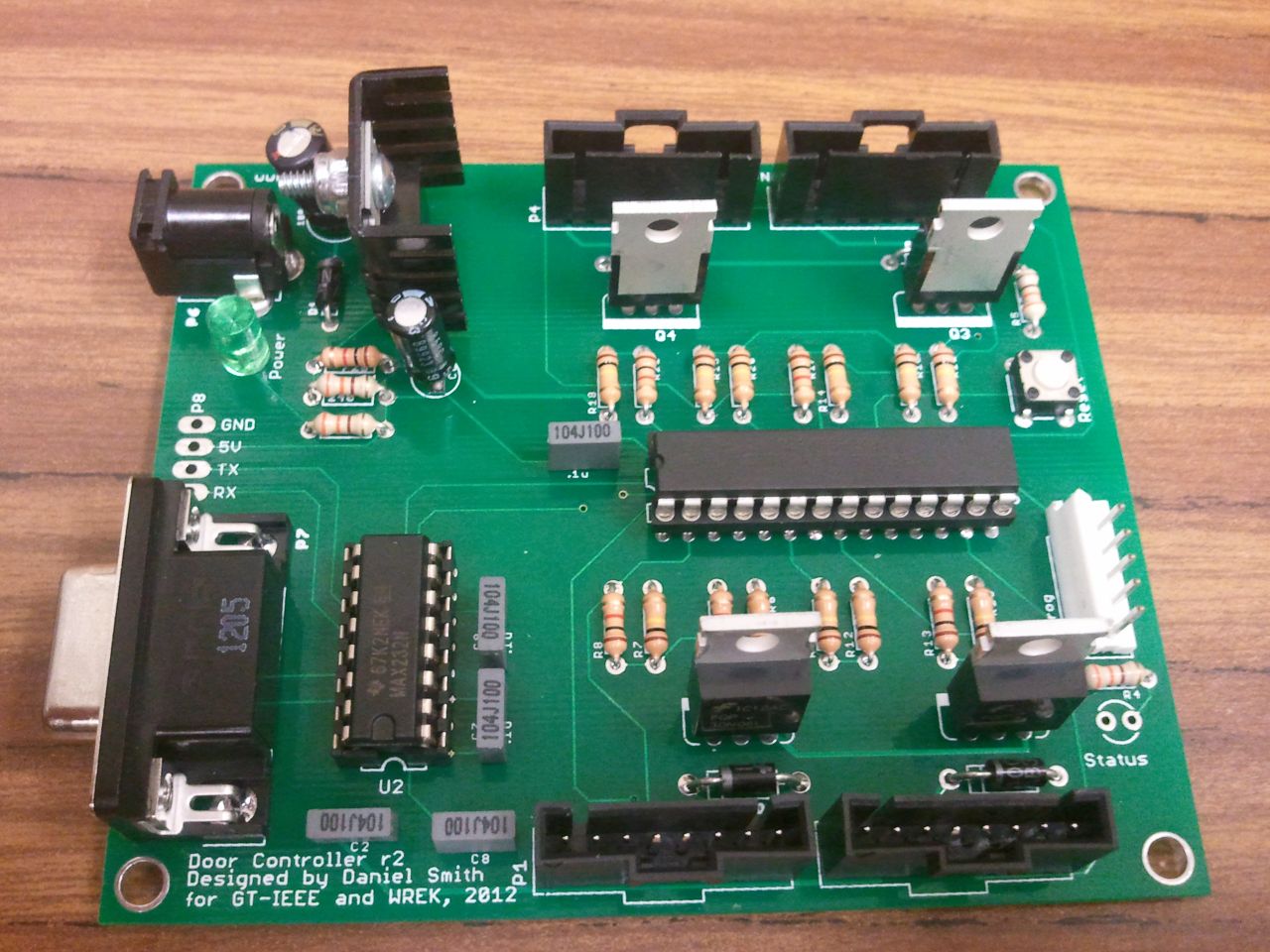
The board was designed to have an input power of 12-14V. The LM317 voltage regulator is biased to have a 5V output for the PSoC and MAX232, but the 12V power is used to supply the RFID readers and door strikes. The power LED is powered from the 5V regulator.
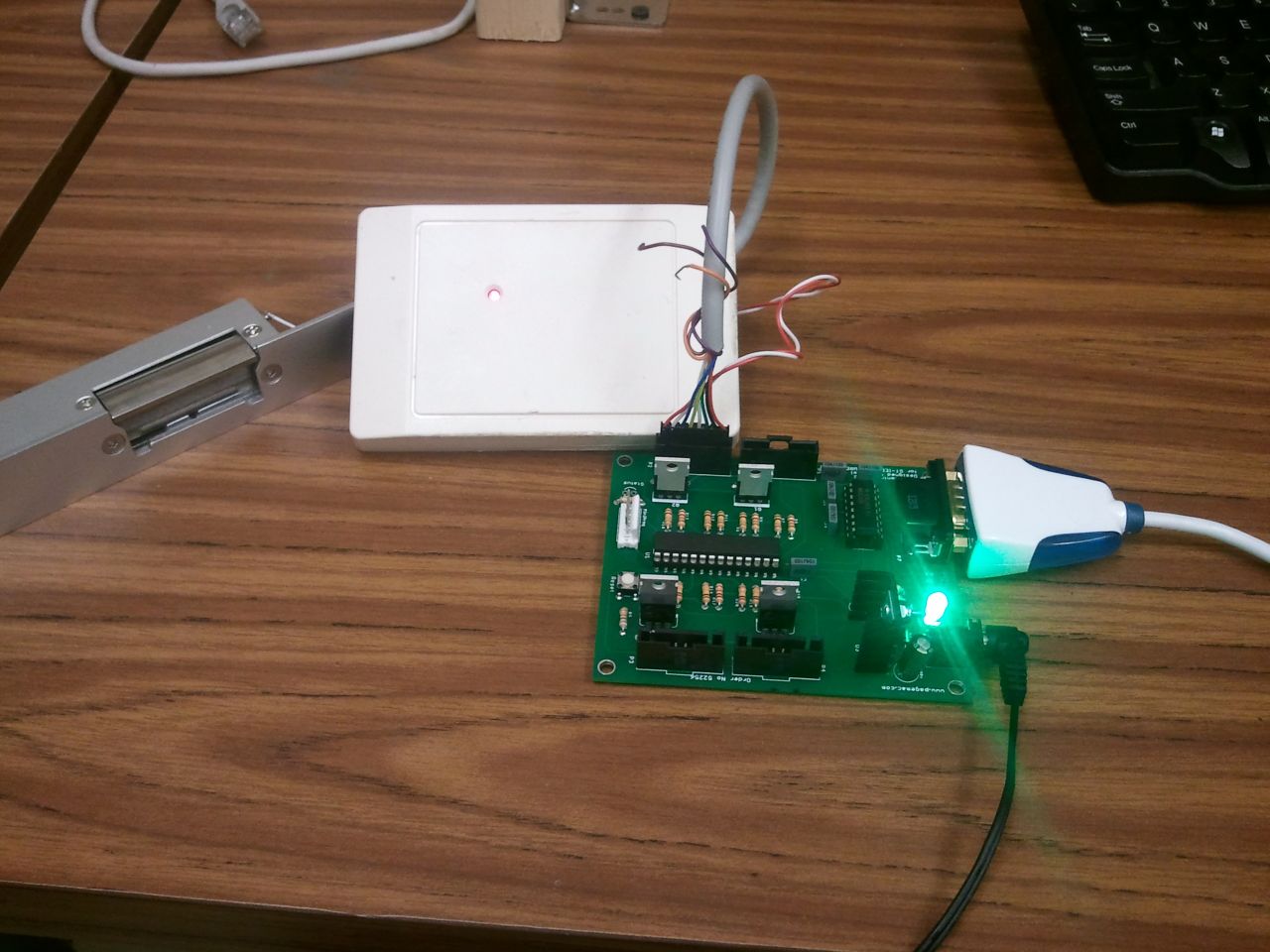
The controller has 4 door ports. Although professional access control systems will have ports for readers, strikes, sensors, alarms, and exit buttons, this system was designed only to have an RFID reader to read card information and electronic door strike to unlock the door. I wanted to run only a single Cat-5e from the controller to each door, which means I had only 8 conductors to use. I used some nice Molex C-GRID III connectors on the board that are polarized. The same connectors are easy to put on the readers. The pinout for the door ports is shown below:
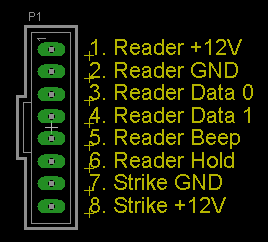
The +12V pins are tied together, but the Strike GND is toggled from an N-MOSFET so that the strike can be controlled from the PSoC. There's also a diode in there for protection from EMF on the strike.
Firmware Description
The door controller system is designed to be operated independant of computer. Previous RFID systems I made would only send card information back over the serial port and require the host computer to validate the credentials. This door controller takes advantage of the PSoC's EEPROM emulation in flash memory.
The controller can store credentials for 504 users. The PSoC is configured to use 4096 bytes of its flash for EEPROM data storage. These bytes are organized in 64 blocks of 64 bytes. The first block is used for controller configuration - number of users, number of readers attached, etc. The other 63 blocks store user information. Each user requires 8 bytes - 2 bytes for facility code, 4 bytes for card code, 1 byte for authorization (allow access to some doors but not others), and 1 unused byte (to keep user blocks on flash block boundaries). This yields 8 users per flash block, or 504 users total.
The Door Controller has a serial interface for programming and logging. This interface has two modes: ASCII and binary. The default mode is ASCII, when status and data is sent in readable characters so that you can interface with the controller with a terminal program (I use TeraTerm). The ASCII mode expects commands in separated by a newline. When configuring the Door Controller with new users, a command is sent to activate binary mode. In binary mode, the first byte received is expected to be the length of the rest of the command. For example, sending two bytes [0x01 0x01] is the “are you there?” command. The first 0x01 indicates an additional 1 byte will be sent. This binary mode makes it easier to copy data directly to the EEPROM.
The RFID readers interface with the PSoC with a Wiegand interface. This interface uses two wires, DATA0 and DATA1 which are normally held high at 5V. When sending data, the DATA0 or DATA1 line is pulsed low for a few microseconds depending on if a 1 or 0 bit needs to be sent. Typically, 26 to 40 bits will be sent depending on the card used. Although I had written a fairly robust Wiegand decoder for a single reader, I had to adapt this code to interface with multiple readers for the Door Controller.
Each DATA0 and DATA1 line for all four readers are configured to be interrupt pins on the PSoC. Each time an interrupt occurs, a 0 or 1 is added to the bit array. After a few milliseconds of not receiving any bits, the PSoC will begin processing these bits. However, if multiple readers send data at the same time, there would be conflict of resources. So, I used the RFID reader's HOLD pin. When this pin is pulled low, the reader will enter a HOLD state. In this state, no data will be sent over the Wiegand interface. If a card is scanned while the reader is in the HOLD state, the reader will stop reading additional cards and “hold” on to the card data. After the HOLD state has been released, the reader will send the data it was “holding” and begin reading cards
Software

The Door Programmer software is a C# utility I wrote to manage the Door Controller. The software is centered around a grid of users. Each row represents a user and contains a facility code, card code and check boxes for access to individual doors. The software can read and write configurations to the device. Additionally, configurations can be saved or loaded from a CSV file. Note that the “User Name” column isn't sent to the controller, it's just used for organization when saved to a CSV file.
When creating a new configuration, just open the program and connect to the COM port where the Door Controller is connected. Enter the number of users you wish to configure. The arrow buttons next to the Number of Users allows you to easily add or subtract rows from the grid. Enter the appropriate credential details and click Send Configuration. The program will convert the data to the proper binary format and send it to the controller. It's recommended that user names are entered and that the configuration is saved to a CSV file for later reference.
When modifying device configuration, open the program and start by loading the previous configuration from a CSV file. Modify the configuration as needed, then send it to the controller. Be sure to save the CSV file again.
Implementation at WREK
Installation at WREK was done in phases. First, just the storage closet door was installed in June 2012. This door is used much less often than the front door, and we just wanted to get an idea how everything would work. After working out a few bugs in the firmware and software, we installed the other 3 doors. There were a few more bugs, and by May 2013 the system had been running quite stable.
Unfortunately by the end of 2014 there were some stability issues. Plans are in progress to replace this controller with a Raspberry Pi-based system.