Sidebar
Table of Contents
Interfacing with an RFID Card Reader
In my Dorm Kiosk project, I mentioned that the apartment complex I live in at my school uses RFID ID cards to enter the complex and individual buildings, though not the actual rooms themselves. The goal of this project is to develop a system that can also read these cards, and eventually integrate it with my Dorm Kiosk.
Exploring the Technology
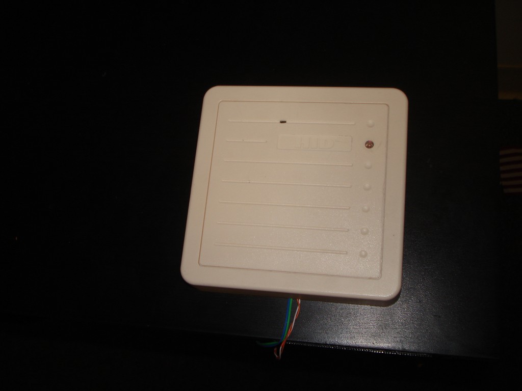
I did not know much about RFID before this project, other than the very basics. I had never played with a card reader, so I went to the source; I checked out the company that makes the RFID system our school uses. Our card readers and ID cards all have the company logo on them. It turns out we use HID, a very large producer of RFID systems. I looked into their products, and visually identified the readers we have. It appears we use their basic, 125kHz Proximity technology. I picked out the most basic reader, the ProxPro 5355. It's the same reader that is commonly found around campus. Unfortunately, they do not have an easy way for individuals to purchase their products, so I checked out eBay. Bingo. Plenty of prox readers available. I grabbed a 5355 for about $20.
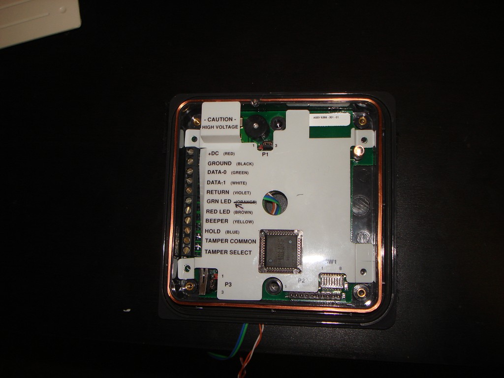
When the reader arrived, I was not sure what to expect. With the help of the installation guide on the HID website, I took the reader apart and found a few clearly labeled wire terminals. Although I did not know exactly how they were used, I found the important ones fairly easily - Ground, DC, Data 0 and Data 1. Of course, now I wanted to power it up, so I put 12 volts on DC and ground. (I got 12 volts from the installation guide). The reader beeped a few times and was powered. Hooray! I waved my ID card in front of the reader, and it beeped and flashed the LED to inform me that the card had been read. Good. It works. Now to get the data. But what are Data0 and Data1?

Wiegand Protocol
Reading more into the installation guide from the HID website, I learned that these data lines were for a data format called Wiegand. I did manage to find some basic information on Wikipedia, which stated that the two data lines represented the binary bits 0 and 1. They are both normally held high. When a 0 needs to be send, the Data 0 line drops low. And when a 1 needs to be sent, the Data 1 line drops low. The voltage levels are typically TTL voltage levels. The pulses are a few microseconds long and the pulse gap is a few milliseconds long.
So this was good. The protocol did not appear too complicated. I hooked the data lines up to an oscilloscope to verify this information, and sure enough, it worked exactly as described. With both data lines hooked up, I could clearly distinguish the bits of data.
Unfortunately, because it uses TTL voltage levels (roughly high=5V, low=0V), this means I would not be able to hook the reader up directly to a computer. I talked to some friends in IEEE, and we agreed a microcontroller would be the easiest way to read the data. The microcontroller could easily be connected to a computer via serial or USB.
Using a PIC
This was my first project learning about microcontrollers. I always wanted to learn how to program a microcontroller, and I finally had friends who know about them and were willing to teach me how it all worked. (gotta love being at GT!) A PIC is a basic microcontroller that is cheap and relatively easy to program in C or assembly.
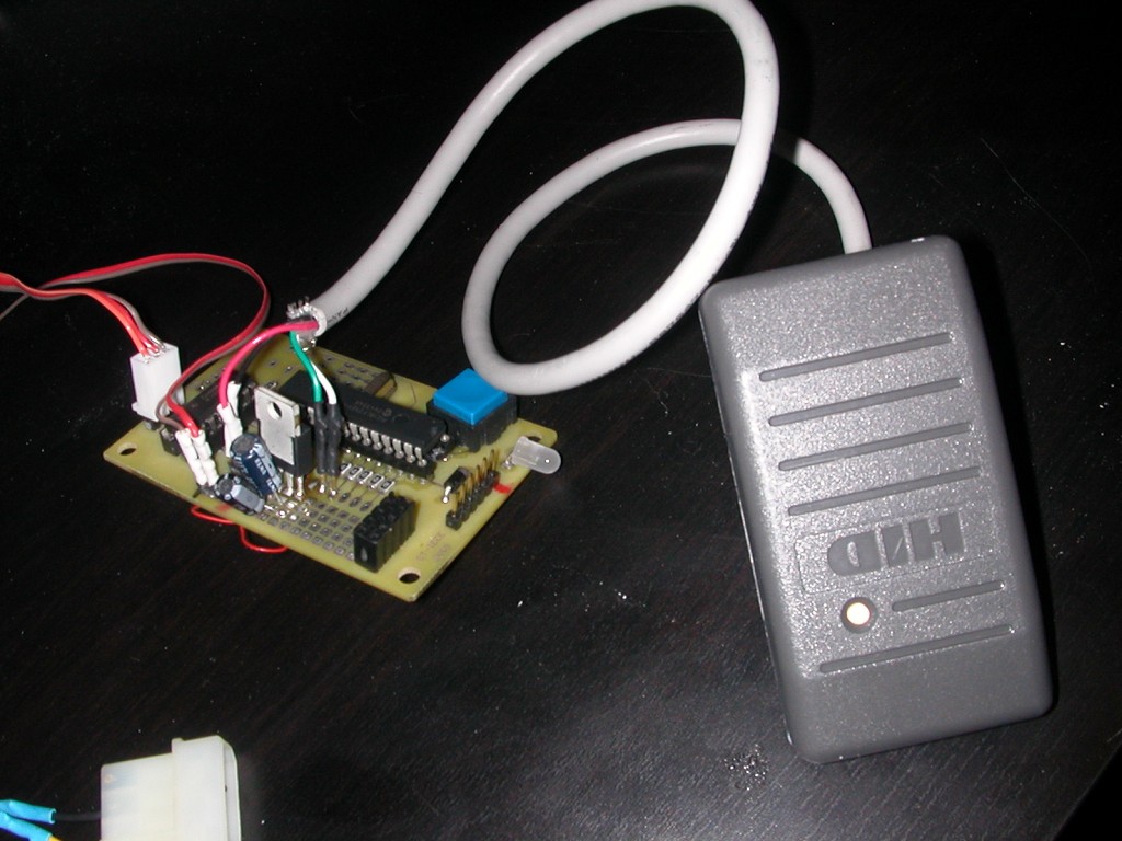
The hardware design was simple. I used a PIC18F2321 because my friend happened to be using one of them at the time. For the PCB, I used a basic board layout that we had in our IEEE student branch lab. I didn't need anything fancy, just the PIC, a crystal, a few resistors and caps, a power regulator, and a MAX232 to shift the serial voltage levels to RS-232 levels so that it could talk to a PC. To interface with the reader, I only needed two headers for DATA0 and DATA1.

The software was also fairly simple. Each of the two data lines were mapped to hardware interrupts. Each pulse would cause an interrupt procedure on the PIC, and that would flip appropriate bits in a byte array. The code can handle up to 40 bits of data. It would be easy to add more, but our ID cards only used 35 bits. When no more data is produced on the line (after 16ms), it formats the data into hex and sends it over serial.
You can download the C source code here.
Prox Reader on the Kiosk
That's it! It only took a few hours to put together. I added some other fun goodies like blinking lights and buttons, and made some wires so it was easy to connect the board to a serial port, the power connector in the computer, and the two data lines and power lines for the reader. It worked perfectly. By presenting a proximity card, the reader would read the card and the computer would recieve the hex bits over serial, followed by a newline. I used Tera Term Pro to view the serial data, but any serial terminal would work (I think HyperTerminal would do it).
Adding support in the Kiosk for the reader was easy. The program would just open the serial port and listen for data, and when it recieved a newline it would process the data. It searches for a user who has that ID card, then toggles that users's status between “Here” and “Not Here”.
Writeup: November 2007
Page Tools
